2. Experimental Techniques
This chapter will discuss in detail the experimental set-up used for the pulsed laser ablation (PLA) and the pulsed laser deposition experiments. The experimental methods used include both plasma analysis techniques and thin film analysis techniques since the main focus of this thesis is to connect the characteristics of the laser ablated species with the properties of the as deposited films.
This chapter divides into three parts, namely the set-up of the laser and vacuum systems, the experimental techniques used to characterise the plume arising during pulsed laser ablation and the experimental techniques used to characterise the deposited films.
2.1. Lasers
The energy source for material evaporation and atomisation in a pulsed laser ablation experiment is a laser. The most favourable wavelengths for these type of experiments are short (UV) wavelengths such as those provided by excimer lasers, for reasons explained in Chapter 3. The popularity of these systems compared with the alternative Nd:YAG lasers stems from their high power output of UV photons without the necessity of frequency doubling (or quadrupling).
The artificial word excimer is an acronym for ‘Excited Dimer’ and characterises a class of molecules that fulfil the conditions for generation of a population inversion: a thermally unstable ground state (well depth of the order of kBT) and excited states with a short radiative decay time (see Figure 2.1).[1] The term excimer actually only correctly applies to homonuclear dimers. The correct term for heteronuclear molecules is exciplex (excited molecular complex), although excimer is commonly used also for the class of exciplex molecules.
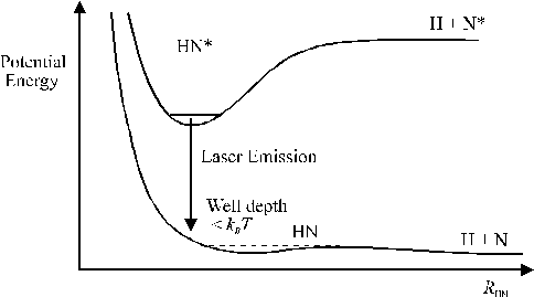
Figure 2.1: Excimer laser operation, specified for an exciplex molecule, where H stands for the halogen atom and N for an inert gas atom and * depicts the excited state.
A transition from the upper electronic state to the electronic ground state results in a fast dissociation (10-13 s) of these molecules into their constituent atoms. For this reason the ground state remains effectively unpopulated; any excited state population will thus constitute a population inversion, which can be used for lasing action. The wavelength of the lasing is determined by the vertical separation of the electronic states; different excimers yield different laser wavelengths. Most excimer lasers are based on inert gas halides such as ArF, although homonuclear excimers, such as F2, also exist. An overview of the commonly used excimer systems is given in Table 2.1, along with their associated lasing wavelength.
|
Excimer Laser |
Wavelength (nm) |
|
F2 |
157 |
|
ArF |
193 |
|
KrCl |
222 |
|
KrF |
248 |
|
XeCl |
308 |
|
XeF |
351 |
Table 2.1: Different excimer lasing systems, each with their characteristic lasing wavelength.
The processes resulting in lasing are given in equations (2.1) to (2.5), where the * depicts an excited state of the molecule and M is the mediating body (or third body in three body reactions). The reactions are given for the ArF excimer laser, the reactions for the KrF excimer laser are similar and the inert gas atom Ar can be substituted by Kr.
|
Ar + e- |
→ Ar* + e- |
||
|
Ar + e- |
→ Ar+ + 2e- |
(Penning ionisation) |
(2.2) |
|
F2 + e- |
→ F + F- |
(Dissociative recombination) |
(2.3) |
|
Ar+ + F- + M |
→ ArF* + M |
(Recombination stabilised by a third body) |
(2.4) |
|
Ar*
+ F2 |
→ ArF* + F |
After lasing, the reaction products can reform the original reactants via reactions (2.6) and (2.7):
|
ArF* |
→ Ar + F + hν |
|
|
F + F + M |
→ F2 + M |
In theory this regeneration scheme suggests that the laser gas mixture should last for ever but, in practise, the laser has to be refilled periodically because the highly reactive F2 degrades through reaction with the laser cavity walls and because of laser cavity leaks. Given the importance of third body reactions, the laser is operated at high pressures (3 atmosphere) and the gas mixture is 0.16% F2, and 6.3% Ar with the balance Ne.
The pulse duration of excimer lasers depends on the pumping mechanism. Pulse durations of tens of nanoseconds are obtained when using electrical discharge excitation. Shorter pulse durations (60 fs – 5 ps) require pumping of an excimer amplifier with the output of a short pulse dye laser. The experimental set-ups for both pumping methods are given in Figure 2.2.
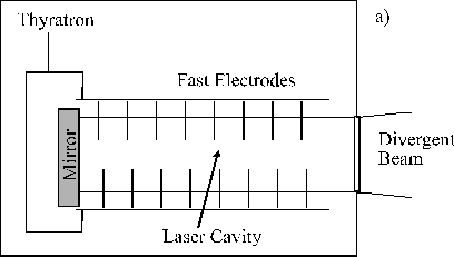
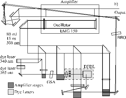
Figure 2.2: Set-up for a (a) nanosecond and (b) femtosecond excimer laser.
In the nanosecond case, high pump powers (in the order of MW/cm2) and pulse durations in the order of tens of nanoseconds can be achieved via fast high-voltage switches (Thyratrons). The short time-scale of the discharge and, more importantly, the typical design of the cavity (shown in Figure 2.2(a)) allows only a single pass of the laser radiation through the cavity, in contrast with the multi-pass cavities used for Nd-YAG lasers. This results in a low degree of mode selection and consequently in low spatial and temporal coherence of the emitted light. The resulting laser beam is highly divergent (1 ´ 3 mrad), the line width is typical 1 nm, and the pulse duration is 10-50 ns. On the positive side, high laser pulse energies (typically 0.1 - 1 J), in the UV spectral range are easily obtainable with excimer lasers.
To obtain an excimer laser pulse of shorter duration a more complicated arrangement involving optical pumping of an excimer amplifier with a short pulse dye laser (shown in Figure 2.2(b)) is required. The EMG 150 Lambda Physik excimer laser is used as a pump laser (at 308 nm) for a special sub-picosecond dye laser amplifier system, and as an amplifier (at 248 nm) for the frequency-doubled output pulses of the dye laser set-up. Part of the output of the XeCl laser is used to pump a Distributed Feedback Dye Laser (DFDL), which in turn generates the pumping laser beam for the KrF laser cavity.[2] This pump source consists of two dye lasers, two amplifier stages and a gated saturable absorber (GSA) placed between the amplifiers. The dye lasers sharpen the leading edge of the laser pulse while the GSA cuts the trailing edge of the pulses. The combined pulse shaping of the dye lasers, amplifiers and GSA results in a ~ 8 ps pulse centred at 365 nm. These pulses are used for pumping the DFDL. The DFDL consists of a coarse transmission grating, a microscope objective and a special dye cell with the active medium (Coumarin 307 dye). The DFDL is a special set-up allowing generation of short, femtosecond pulses from a seeding pulse of longer pulse duration. The mechanism works via imaging an interference pattern of a seeding laser pulse onto the wall of the dye cell via a grating. The output wavelength of the DFDL is set to twice the KrF wavelength (496 nm). The output of the DFDL is again amplified via a two-stage amplifier, separated by a saturable absorber and frequency doubled by a Beta-Barium Borate (BBO) crystal to yield pico- or femtosecond seeding pulses of 248 nm wavelength. This seeding pulse pumps the second cavity of the EMG 150 laser filled with KrF, via a double pass arrangement shown in Figure 2.2(b), yielding pulse energies in the range 10-15 mJ with pulse length 450 fs. 5 ps laser pulses can also be generated by insertion of a multiple reflection etalon in the dye laser set-up.
In both cases the output power was recorded by two different means. The output power was recorded via a beam splitter and power detector arrangement built into the laser housing, and measured independently using a Joule stick or a power monitor. To allow fine adjustment of the laser output into the vacuum chamber the laser beam was directed onto the target via two highly reflective mirrors held in kinematic mounts.
2.2. Vacuum chamber
The vacuum chamber for the ArF work consists of a cylindrical stainless steel vessel with internal diameter of 260 mm and height of 160 mm. The basal plane of the chamber is mounted on the table and pumped by a 100 mm turbomolecular pump (Leybold Turbotronic NTL59/369) backed by a two stage rotary pump (Leybold Trivac). The pumping system could be isolated from the vacuum chamber via a ‘butterfly’ valve. The top of the vacuum chamber consists of a large flange that can be removed to access the chamber. Ten additional flanges are connected on the walls of the vacuum chamber to mount pressure gauges, a (reactive) gas inlet, electrical feed-throughs, substrate and target holders, backing pump (rotary), laser input window and the Faraday Cup/Quadrupole Mass Spectrometer (QMS) assemblies. The vacuum chamber assembly for the KrF laser ablation studies was slightly different, primarily with regard to the means of mounting and using the optical emission assembly and CCD array. This will be described at the appropriate point later in this chapter.
The pressure in the chamber used for the ArF laser ablation studies is measured by Pirani and Penning gauges (Edwards) and a baratron (MKS). The range of pressures measurable with this assembly is 5 ´ 10-8 to 10 Torr. A typical base pressure maintained in the ablation chamber was ~10-6 Torr. Throughout this work, ablation/deposition conditions described as vacuum will refer to a base pressure of ~10-6 Torr. When required, a (reactive) background gas was introduced into the chamber via a Mass Flow Controller (MFC, Tylan) up to pressures of ~50 mTorr. Pressure readings were obtained from the Pirani gauge and the baratron. Typical gas flows were ~5 sccm. This assembly allowed a controllable and precise gas flow and enabled stable and reproducible pressures over typical deposition times of 15 minutes.
The top flange of the vacuum chamber for the ArF work also supports a large rectangular quartz window (90 ´ 45 mm2) thus allowing for measurements of optical emission from the plasma plume. The optical emission assembly for the KrF work is mounted so as to view through one of the side flanges, equipped with a quartz window. The CCD camera imaging was performed either through a polished poly-methyl-methacrylate (PMMA) top flange (ArF work) or via a window in the horizontal plane at the height of the target holder (KrF work). These differences are shown in Figure 2.3.
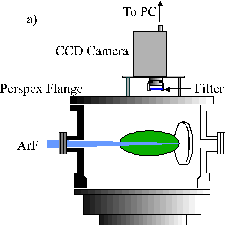
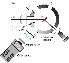
Figure 2.3: The two different set-ups used to monitor OES in the laser ablation experiments using (a) ArF and, (b) KrF laser irridiation.
The entrance window through which the laser beam passes consists of a 50 mm diameter quartz flat in both ablation chambers. During laser ablation, material is unavoidably deposited onto these windows. This results in some attenuation of the incoming laser light as the thickness of the film deposited on the entrance window increases with time, which hampers estimation of the laser fluence reaching the target surface. Because of this, the laser window is replaced after every 15 minutes (9000 shots) of laser operation during deposition. In the case of laser ablation studies the windows were exchanged after ~3000 shots to ensure a constant, measurable laser fluence. The film deposited on the laser window was removed afterwards, by heating in air in a Bunsen flame in the case of deposition of Diamond Like Carbon (DLC) or by placing them in ‘Aqua Regia’ in the case of metal or zinc oxide deposition.
2.3. Target Materials and Holder
2.3.1. Target materials
The target materials used in this thesis are 2 inch diameter disks of Highly Oriented Pyrolytic Graphite (HOPG, Poco Graphite Inc., DFP-3-2 grade) and high purity ZnO (99.99 % pure, Testbourne). For the doped ZnO studies, sintered disks consisting of 5% Al or Ga and 95% ZnO (Testbourne) were used. The ablation of metal was performed with commercially available 2 inch diameter Cu or Al disks.
2.3.2. Target holder
Two different target holders were used in the ArF laser ablation studies. The first assembly consists of a rotating target (typically 1 rpm) directed at an angle of 45° with the incoming laser beam. It is rotated by a stepper motor mounted on the outside of the vacuum chamber. The rotation speed is chosen to be fast enough to provide a fresh target surface for every shot, although on typical deposition times (15 minutes) every spot on the ablation track is used 15 times, causing groove formation in the target. A drawback with this arrangement is that only a very small part of the target surface is used for ablation (only the laser track) and, since the target surface is polished after 15 minutes of ablation to reduce track formation, a large part of the target surface is removed without being used.
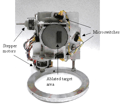
Figure 2.4: A photograph of the (x,y) translation stage used in the ArF laser ablation.
The second assembly houses the target in an (x,y) translation stage (shown in Figure 2.4). The stepper motors that drive this assembly are mounted in the vacuum. In this assembly the target is stepped in both the x and y directions while the laser interaction spot is held stationary. The advantages on this set-up are (i) that the target surface can be ablated much more efficiently and for a longer time duration without groove formation and (ii) that the complete assembly can be rotated (about the vertical axis) relative to the incoming laser beam, thus giving a greater versatility. One of the main disadvantages is that operating the stepper motors in vacuum can cause them to overheat at longer time scales, because of the poor temperature conduction in high vacuum, leading to assembly failure. Introduction of stepper motors in vacuum also increases the introduction of contaminants (oils), degrading the vacuum conditions and necessitating longer pumping times.
2.4. Plasma Detection Equipment
The laser ablation event at high fluences (typical > 1 J/cm2) produces a time evolving plasma cloud. This plasma can be studied by a number of different techniques. The easiest and most common techniques for analysing the plasma are optical emission spectroscopy and electrical probes. The optical emission arising from the plasma can be viewed time independently or time dependently using a quartz fibre to couple the emitted light into a monochromator/photomultiplier assembly or by time gated CCD imaging. The total ion and electron current in the plasma can be detected by electrical probes and can be studied time dependently using a Langmuir probe or a Faraday Cup assembly. In addition, the plasma can be studied by Mass Spectrometry. This technique allows for mass separation of the detected particles and for detection of the neutral particles in the plasma. In addition, the intensity and temporal profile of the laser pulse can be studied after passage through the ablation plasma, revealing any attenuation effects of the laser light by the expanding plasma. This effect is studied using a special set-up discussed below.
2.4.1. Optical Emission Spectroscopy
Optical emission from the plasma formed by the incident fluences used in the present work are clearly visible by eye. This emission can be studied with the assembly shown in Figure 2.5. The optical emission arising from the detection column in the plasma is focused by a lens through an iris onto the front end of a quartz fibre optic bundle (Oriel). The rear end of the fibre optic abuts the entrance slit of one of the two monochromators used in this study and described below. The input end of the fibre optic is circular (3 mm diameter) and the output of the fibre is a 1 ´ 7 mm2 rectangular slit to match the entrance slits of the monochromators. The viewing column in the focal point of the lens, aligned so as to sample the plasma plume along the target surface normal, has an estimated diameter of 2 mm, indicating the minimal experimental error on the spatial measurements made with this assembly. The whole assembly can be translated in two orthogonal directions in the horizontal plane (see Figure 2.5) to provide spatially resolved measurements.
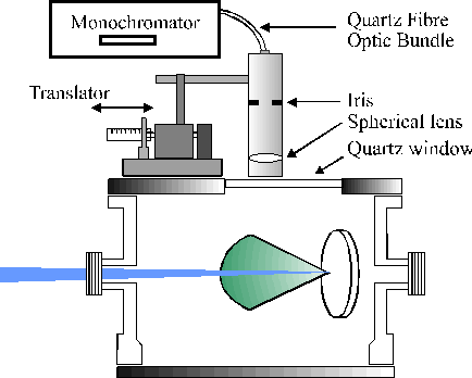
Figure 2.5: Experimental assembly for wavelength dispersed optical emission spectroscopy.
For the ArF work two monochromators were employed. One was a 12.5 cm monochromator, equipped with a 600 lines/mm ruled grating and a UV extended Instaspec IV CCD array detector. With this arrangement, time integrated, low-resolution (0.9 nm) dispersed emission spectra over a wavelength scale of 225-1025 nm could be recorded. Synchronisation of the detection system with the laser ablation event and summing over a number (typically 30-250) of shots obviously greatly enhances the signal to noise ratio of the measured spectra. The spectra are wavelength calibrated by recording the dispersed emission spectrum of the room lights, which contains strong mercury emission lines. The spectra are presented uncorrected for the wavelength dependent quantum efficiency of the grating and the CCD array detector unless stated otherwise. The overall detection sensitivity peaks at ~620 nm and is four times lower at the two extremes of the wavelength range investigated (i.e. 225 and 1025 nm).[3]
The second monochromator is a 0.5 m Spex 1870 equipped with a 2400 lines/mm holographic grating. Photons transmitted through the monochromator are detected using a red sensitive fast Photo Multiplier Tube (PMT). Wavelength calibration of this spectrometer involved recording and measurement of well-documented Ne emission lines from a neon hollow cathode lamp. This monochromator/PMT assembly allows measurement of the intensity associated with a specific emission feature as it expands through the viewing column, simply by positioning the grating of the monochromator so as to transmit the wavelength of the emission line of interest and monitoring the transient emission signal as a function of time after the laser pulse is incident on the target. The entrance slit width to the monochromator is user-selectable and was chosen to be 400 mm. The output of the PMT is directed to a digital oscilloscope (LeCroy 9361, 2.5 GHz sample rate) and is stored via a GPIB interface on a PC. Zero time was established accurately by monitoring the scattered radiation from the iris in the beam line immediately in front of the entrance window of the ablation chamber. These transient signals are summed over 30-250 shots (depending on the intensity of the line) to enhance the signal to noise ratio.
2.4.2. CCD camera imaging
Two different set-ups were used for the CCD camera imaging studies. The first consisted of a CCD camera mounted on the top flange of the chamber and was used in Chapter 4 (ArF work). The second consisted of a CCD camera mounted on the side of the chamber so as to view in the horizontal plane. This was used in Chapter 6 (KrF work). The two different set-ups were shown schematically in Figure 2.3. The i-CCD camera used in the set-up shown in Figure 2.3(a) and discussed in Chapter 4 uses a Photonic Science camera equipped with a time gated image intensifier. The typical time gate used was 0.1 ms. The camera is mounted in the vertical plane in the laboratory frame. A Pentax 25 mm TV lens imaged the ablation plume onto the CCD array yielding a squashed 2-D (xy) projection of the full 3-D plume of emitting particles. The set-up in Figure 2.3(b) uses an intensified and gated CCD array (iStar 720D Andor Technology) as an i-CCD camera. The camera was mounted in the horizontal plane in the laboratory frame. The image was projected onto the 1024 ´ 256 CCD array by a confocal lens with 20 cm focal length, in a set-up that gave a 2:1 magnification.
Images recorded were either of the total emission or of selected emission lines, by viewing through appropriate optical filters. The intensifier was triggered by the signal of a fast photodiode monitoring scattered radiation from the ablation laser pulse.
2.4.3. Langmuir Probes
Langmuir probes are one of the simplest techniques for obtaining information about the ions in a plasma. They consist of an electrode of known area inserted in the plasma and connected electrically to a variable-voltage power supply (see Figure 2.6). This power supply is in turn grounded to a reference electrode inserted in the plasma. The reference electrode in the case of a single Langmuir Probe is much larger than the probe itself and typically consists of the chamber walls or any other convenient conducting surface in contact with the plasma. This apparently simple experimental technique is associated with rather complicated theories that are needed to explain the current-voltage behaviour of these probes in a plasma.[4]-[6] Thus we start by providing theoretical background to the technique.
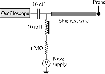
Figure 2.6: Set-up of the electrical connections for the Langmuir Probe.
2.4.3.1. Theory of Langmuir Probes
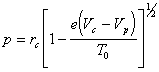
The probe current is dependent on the potential imposed on the probe. A typical current-voltage plot is shown in Figure 2.7. This characteristic is normally determined by the plasma properties in the immediate vicinity of the probe.4-6 The general shape of the I-V characteristic can be divided into three parts. When the probe is biased positively with respect to the local plasma potential the flux of particles reaching the probe will consist of carriers of negative charge (normally electrons). This region is called the electron accelerating region and is labelled III in Figure 2.7. These electrons will be collected from a region called the sheath, which is the region close to the probe surface where the potential exerted by the probe is not shielded by the plasma. When the probed is biased at a potential slightly smaller than the plasma potential only particles with enough energy to overcome the potential barrier will be collected. This region (region II in Figure 2.7) is called the electron retarding region. The third region is accessed when the probe is biased increasingly negative relative to the plasma potential. In this region (region I in Figure 2.7) only positive ions will reach the probe. This region is called the ion saturation region. The governing theories applicable to these three regions in the I-V plot are discussed in the remainder of this section.
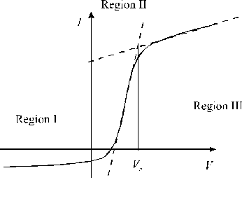
Figure 2.7: Typical current voltage plot, Vp represents the plasma potential.
The electron-retarding region (region II) is the easiest to describe and will be discussed first. In this region the probe actually acts as an energy selector, collecting only those electrons which have large enough kinetic energies to overcome the potential barrier. If the electron distribution is in local thermal equilibrium, the electron energy distribution function can be assumed to be Maxwellian and the current drawn in this regime follows the relation 6
|
(2.8) |
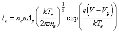
where Ie is the electron current, ne the electron number density, e the electron charge, Ap the probe area, k the Boltzmann constant, Te the electron temperature and me the electron mass. The gradient of a plot of ln[Ie] versus the applied voltage, V, yields the electron temperature and, given knowledge of the electron current at the plasma potential, substitution of Te in Equation (2.8) yields to the electron number density.
The electron acceleration region (III) is governed by the orbital motion theory, and an expression for the electron current in this region can be derived as follows: consider a point charge at a bias potential Vb, separated from an electron with charge e by a distance r0 where the potential is Vp. Assume that the electron has a forward trajectory, with velocity v0 and impact parameter p as defined in Figure 2.8.
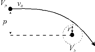
Figure 2.8: Schematic of the input for the orbital motion theory.
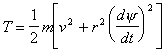
The total kinetic energy T of the particle at any time during its trajectory is given by:
|
|
|
where the two terms on the right hand side of expression (2.9) are, respectively, the translational and the rotational parts of the total kinetic energy. Given that (conservation of angular momentum):
|
|
(2.10) |
we can rewrite the expression (2.9) as:
|
|
Given equation (2.11) we can rewrite the total energy of the system as:
|
|
At the point of closest distance to the probe (rc), the translational kinetic energy is totally converted into centrifugal energy (v = 0), thus the total energy expression (2.12) can be rewritten as:
|
|
Rearranging expression (2.13) gives:
|
|
(2.14) |
Taking rc as the probe radius a, any particle with p < a[1+(Vc-Vp)/T0]1/2=pa will be collected. The expression for the current collected by a cylindrical probe given a Maxwellian electron velocity distribution can also be derived (analogous to (2.8)). It takes the form:
|
|
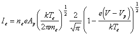
Plotting the square of the electron current against the probe voltage yields a straight line, the gradient of which provides a measure of (ne)2.
The ion saturation current region (I) is a more difficult region to describe. The amount of ion current is governed by the Bohm criterion, since the ion temperature is much lower than the electron temperature in the plasmas under consideration. The Bohm criterion states that the ion velocity must acquire a positive (towards the probe) velocity at the plasma sheet edge even when the ions have very low temperatures. This velocity is provided by the existence of a “pre-sheet” potential drop that occurs at long distances in the plasma. The ion current is thus dependent on the electron temperature and is given by:
|
|
|
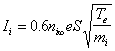
where ni,¥ is the unperturbed (by the electric field of the probe) ion density and S is the surface area of the probe.
Since the ion current is dependent on the electron temperature there is no easy way to deconvolute the total signal into the ion density and the electron temperature without independent measurement of one of the parameters.
The above expressions are strictly only valid in collisionless sheath conditions (i.e. when the mean free path l > sheath dimensions). Higher order corrections have to be included in the expressions in situations where collisions occur within the plasma sheath.
2.4.3.2. Langmuir probes in laser ablation
Most electrostatic probes used in ablation plasmas are ion probes.[7] Ion probes have the advantage that data can be acquired faster; most ion probe work is performed at one set voltage while, with a Langmuir probe assembly, the voltage has to be swept over a range of voltages to obtain information about the electron distribution. As can be seen from equation (2.16) the use of cylindrical ion probes close to the target can be problematic if one wants to deconvolute the ion density from the electron temperature. A better method for measuring ion densities involves use of a Faraday Cup assembly, at larger distances from the target, where the particles propagate essentially in a free flight regime.
Langmuir probes are employed in laser ablation studies, particularly to obtain more information about plasma parameters, such as the electron density and temperature and, more importantly, to learn about the transient characteristics of the plume. Absolute measurements of the electron density and the electron temperature are less important since their values depend strongly on the distance and time delay of measurement. Relative measurements of the density transients suffice to provide a TOF distribution from which the velocity distribution of the electrons can be derived.
The theory associated with the use of Langmuir Probes in laser ablation plasmas has been studied in depth by Weaver et al.[8] Since the standard Langmuir probe theories generally apply to static plasmas some specific considerations have to be taken into account. Under the ablation conditions prevailing in their study -which are very comparable with the conditions used in this work- it has been shown that the Langmuir probes operate under collisionless sheath conditions. Under these conditions, it can be shown that the I-V characteristics of the probe are well approximated by those of a static, non-flowing plasma, provided the root mean square thermal velocity of the electrons in the plasma is at least three times greater than the local flow velocity.[9] Given a local flow velocity and the standard conditions during laser ablation, the electron temperature has to be greater than 0.04 eV. This condition is easily satisfied during laser ablation, the values derived from the study of Weaver et al. 8 yielded values for the electron temperature of > 1 eV for the moderate fluence (5 J/cm2) laser ablation of copper.
2.4.3.3. Specifics of the Langmuir probe
The Langmuir probe assembly consists of a Tungsten wire, 125 mm in diameter and 8 mm in length, supported by a glass sleeve (see Figure 2.6). The wire can be biased at voltages in the range of -30 to 30 V, relative to the target and the vacuum chamber, with a stabilised power supply coupled to an electrical circuit that enables the probe to be maintained at a constant bias while passing the transient current due to charged material in the ablation plume to the oscilloscope. Great care was taken to prevent the probe feed wires being exposed to the plasma since this will contribute to the measured probe signal. To ensure a clean probe surface, the probe wire is replaced every ~ 10,000 shots, although no signal attenuation due to material deposition on the probe was observed during the experiments.
The output of the Langmuir probes was directed to a digital oscilloscope (LeCroy 9361, 2.5 GHz sampling rate) and then, via a GPIB interface, to a PC for storage and data processing. Zero time was established by monitoring the signal from a fast photodiode positioned so as to detect a fraction of the laser output pulse.
2.4.4. Faraday Cup
A second way to study the ions in the plasma involves use of a Faraday Cup assembly. This detector consists of a polished stainless steel plate, 15 mm in diameter, mounted 4 mm behind an annulus supported, 85% transmitting, grounded tungsten mesh. The front face of the plate was positioned at a distance d = 421.7 mm from the focal spot, along the surface normal (thus the plasma propagation axis). The stainless steel flat was maintained at a voltage of –20 V to repel the electrons in the plasma, while the mesh was held at ground potential. The plasma was measured behind a 2 mm pinhole to enable higher resolution angular measurements. A schematic of the set-up is given in Figure 2.9.
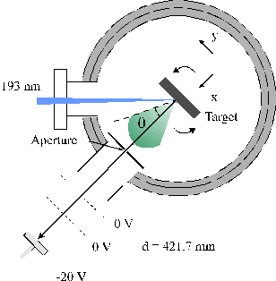
Figure 2.9: Faraday Cup assembly
The Faraday Cup was used in combination with the target (x,y) translation stage. This set-up can also be used to provide information about the angular distribution since this translation stage can be rotated around the laser interaction region. Rotating the target will have implications on the laser footprint on the target and on the interaction of the laser beam with the ablation plume (we show later that the radial distribution of the flux in the ablation plume can be described as a cosqq relationship, where q is the polar angle defined relative to the surface normal). The influence of these parameters on the incident laser fluence is assumed to be small for small (q ± 20 °) angular variations. The angular distribution obtained by these measurements is peaked along the surface normal assuring this assumption, as will be described in Chapter 4.
2.4.5. Mass Spectrometer
This project also involved commissioning and evaluating a state of the art Quadrupole Mass Spectrometer (QMS, HIDEN, HAS-5PL-4353). A short introduction to the operation of this instrument is given in this paragraph. A more detailed characterisation of this apparatus is presented in Appendix 2. The internal structure of the mass spectrometer is given in Figure 2.10. It consists of 5 key parts, namely the extraction region, the source region, the electrostatic analysis (ESA) region, the quadrupole mass filter (QMF) and the detection region incorporating a secondary electron multiplier (SEM).
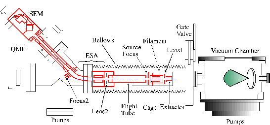
Figure 2.10: Schematic of the electrostatic lenses in the mass spectrometer. ESA stands for the electrostatic analyser, QMF stands for the quadrupole mass filter and SEM stands for the secondary electron multiplier.
The extraction region consists of two electrostatic lenses, the extractor lens and a lens to focus the ions into the source region. The extractor lens is mainly used to extract ions out of a stationary or thermal plasma and is (because of the high directionality of the ablation plasma) of minor importance for laser ablation plasmas. The second focusing lens (lens 1 in Figure 2.10) plays a more important role during operation of the mass spectrometer. This will be discussed in greater detail in Appendix 2. Since this region precedes the source region of the QMS, the electric fields generated by these extractor lenses only affect the trajectories of the ions, not the neutrals, entering the QMS.
The source region consists of a tuneable electron impact ionisation source and a focusing lens. In this region neutral particles can be ionised by electron impact and focused into the electrostatic analysis region.
The electrostatic analysis region is the energy filter of the mass spectrometer. It consists of a field free region which is on a variable potential. After the field free region only the particles with a given kinetic energy (20 eV) will be deflected through the necessary 45° to enter the centre axis of the subsequent quadrupole mass filter and thus reach the detector. Particles with other kinetic energies will not be deflected through the ideal 45° angle and will subsequently not be detected. Energy selection is obtained by changing the voltage on the field free region; by ramping this voltage particles with different initial kinetic energies will be progressively accelerated to the required kinetic energy for optimal deflection towards the detector, thus allowing measurement of a kinetic energy distribution. Unfortunately this set-up for energy selection exhibits a number of problems when applied to laser ablation studies, as will be discussed in Appendix 2.
The Quadrupole Mass Analyser is a standard quadrupole mass filter and the detector consists of a secondary electron multiplier.
2.4.6. Jacobian Transformation
An obtained TOF profile can be transformed into its corresponding velocity distribution by a non-linear Jacobian transformation. In practice, this can be done by rebinning the original TOF signal, which is recorded in a number of equal time increments (or bins). Thus the total signal in a given time bin has to be adjusted, by dividing by the bin length, while maintaining the same total signal, in order to convert the horizontal axes of a TOF profile (time) to a velocity distribution (velocity), since these are connected in a non-linear way (v = d/t). To obtain the same total signal for the TOF and velocity distribution the horizontal axis of the TOF distribution is first converted into a non-linear velocity scale. The amount of signal in every bin is then redistributed in a linear velocity scale, by considering the degree of mutual overlap between the nonlinear and linear bins. This procedure is of course easily implemented in a computer code, which has been written in FORTRAN77. The correctness of the routine was monitored by both calculating the mean velocity for the TOF and velocity converted distributions and by comparing the total amount of signal before and after conversion. Both distributions have to give the same value for both of these quantities, since neither should be affected by the transformation.
2.4.7. Determination of the attenuation of the laser light by the ablation plasma
The set-up for measuring attenuation of the laser light by the ablation plume is given in Figure 2.11. The output of an excimer laser (Lambda Physik, Compex 201) operating on ArF (193 nm, 10 Hz repetition rate, output energy £ 300 mJ pulse-1) was steered using two (or three) dichroic mirrors and focused (20 cm focal length lens) so as to be incident, along the surface normal, on a graphite target located in a stainless steel vacuum chamber maintained at ~10-6 Torr. The target (0.75 mm thickness) has a small hole mechanically drilled through the surface so as to transmit a fraction of the laser light (for eventual detection). The transmitted light is attenuated further by reflection off 2 quartz flats (reflection ~10 % in each case) and steered through a monochromator set so as to transmit only 193 nm light before detection on a fast photodiode. The current on the photodiode is recorded on a digital oscilloscope (50 W terminated, LeCroy 9361) and then transferred via a GPIB interface, to the PC for storage and subsequent data processing. Attenuation of the light by reflection off the quartz flats was necessary so as not to saturate the photodiode.
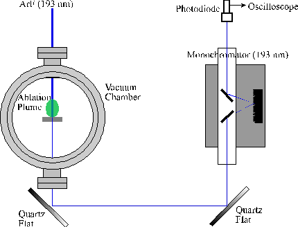
Figure 2.11: Set-up for the attenuation experiment
2.5. Film deposition
Deposition runs were typically performed at fluences between 10 and 25 J/cm2 dependent on the material to be deposited. Deposition times ranged between 2 and 15 minutes at a laser frequency of 10 Hz, and the substrates were mounted at a distance of 4 to 7.5 cm from the target. The background pressure for deposition is dependent on the film material sought and ranges between high vacuum (10-6 Torr) and 10 mTorr.
The substrate material was typically Si(100) wafer cut into pieces of 1 cm2 surface area. UV-visible absorption spectroscopy measurements required film growth on fused quartz substrates also. The use of clean substrates is of the utmost importance if a coherent film is to be obtained. Both the quartz and silicon substrates were cleaned with ‘aqua regia’ and methanol before deposition.
The substrates were mounted either on a carousel, on which four substrates could be mounted simultaneously, or on a heated substrate holder. During deposition with the former arrangement, exposure of just one substrate to the ablation flux can be assured by rotating a shield associated with the carousel so as to mask all bar the one substrate of interest. This enables deposition of four different films without opening the vacuum chamber. The substrate heater consists of a 100 W halogen light bulb (8 A, 12.5 V), in contact with a small copper substrate holder on which one substrate could be attached. This set-up enables substrate temperatures £ 500° C to be reached, as measured with a calibrated thermocouple.
2.6. Film analysis techniques
2.6.1. Raman Spectrometry and Photoluminescence spectroscopy
Laser Raman spectroscopy (LRS) provides information on the phonon structure of the deposited films. As discussed later, this phonon structure is critically sensitive to the quality of the deposited films. Photoluminescence (PL) spectroscopy provides information about the electronic structure of the material -another property that is also highly dependent on the quality of the films. Both of the analysis techniques can be used as tests of the quality of deposited films.
LRS was performed at a number of excitation wavelengths, 488
nm laser excitation was achieved using by an Ar+ laser (Spectra
Physics 12000) coupled to a Renishaw Ramanoscope (G52836). This provides ~4 mW on
the sample in a spot diameter of ~3 – 4 mm. The
same set-up was used to record spectra following excitation at the other Ar+
laser line (514 nm), in this case with up to 20 mW power focused into a ~1 mm spot.
Spectra taken at 325 nm were obtained using another Renishaw Ramanscope
(G92360) and operating with a Kimion K series HeCd laser which provided ~3 mW
on the sample in a spot size of ~2 mm.
Each spectrum is typically an accumulation of 10 scans and is calibrated by the Si(100) peak at 520 cm-1. Photoluminiscence was obtained with the 325 nm excitation wavelength, with all the procedures the same as for the Raman spectrometry.
2.6.2. Scanning and Transmission Electron Microscopy
The surface structure and the thickness of the deposited films can be imaged by scanning electron microscopy (SEM), while the nanoscale structure and crystallinity of the material can be investigated by TEM.
Scanning electron microscopy was performed with a Jeol SEM 5600 LV system, while TEM used a Jeol TEM 2010 instrument, and high-resolution images were obtained using a Jeol SEM 6330 FEG. For the higher resolution images it was necessary to first coat the films with platinum in a sputter source so as to obtain better contrast. The microscopes also have the facility for EDX (Energy Dispersed X-ray) spectroscopy, which can provide information on the surface composition both of the target materials and the deposited films. These X-rays are generated by the high-energy electron (10-20 keV) impact on the surface of interest and are detected using a SiLi detector, calibrated with respect to cobalt metal emission (6.925 keV). Quantitative analysis was carried out by using the Oxford link Isis system.
Films for TEM analysis were deposited on mica pre-coated by a sputtered DLC film and post processed to yield stand alone thin films. For this application the films were typically deposited for 2 minutes. It was possible to perform planar TEM on these films.
2.6.3. Ultra-Violet and Visible Spectrometry
The Ultra-Violet/Visible (UV-VIS) spectrum of a material provides information about its optical properties, which are directly related to its electronic properties. It provides information on the optical band gap, sub-band gap absorption etc. and can also be used as an indicator of the quality of the deposited films.
UV-VIS absorption spectra were recorded on a Perkin Elmer Lambda Bio 10. The radiation sources in this spectrometer are deuterium and halogen lamps (lamp crossover at 326 nm) giving a full range of 200-900 nm, an accuracy of ± 0.5 nm and a spectral bandwidth of 2 nm. Absorbances of films grown on quartz substrates are taken against a background reading of a blank quartz film using UV Winlab™ software on a PC.
2.6.4. X-ray diffraction
X-ray diffraction gives an insight into the crystalline structure of a given material, since the interplanar spacing in regular crystals is of the order of the wavelength of X-ray radiation. Irradiating a crystal with a collimated and mono-energetic X-ray source gives rise to constructive and destructive interference via scattering of the X-rays of the crystal planes. Given the situation in Figure 2.12, where the crystal planes of the sample make an angle of q in respect with the X-Ray source and the detector is situated at an angle of 2q with the X-Ray source. To obtain constructive interference the path length A-B-C has to be equal to an integer multiple of the incident wavelength. This leads to the formulation of Bragg's law (2.17):
|
|
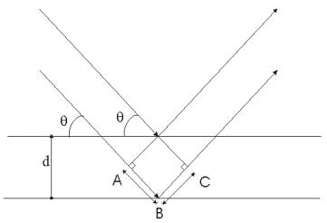
Figure 2.12: Figure explaining the Bragg equation.
where l is the wavelength of the X-rays, d is the interlattice spacing, q is the incident angle and n is an integer. Different crystal planes will have different diffraction angles. In this way X-ray diffraction gives essential insight in the alignment of the film. Deviations from the ideal refraction angle indicate perturbations of the interlattice spacing. Such deviations can be caused by internal stresses (smaller d) or deviations from the ideal stoichiometry. A further determination of the crystal structure is provided by recording rocking curves of the samples. Obtaining a rocking curve involves rotating the target while the X-ray source is kept stationary. Rocking curves can give a measure of the misalignment of the individual crystallites in the film.
X-ray diffraction spectra were measured on films grown on Si(100) and quartz substrates using a Bede D1 system and an X-ray wavelength of 1.54056 Å (Copper Ka). Spectra were calibrated with respect to the (100) silicon substrate peak.
2.6.5. Atomic Force Microscopy
With Atomic Force Microscopy (AFM) the surface of a material is probed with an atomically sharp tip, which is attached to a flexible cantilever. The cantilever deforms under repulsive interactions between the surface and tip atoms. The cantilever tips are usually made from Si3N4, and have a 5 nm surface area. The deformation of the cantilever (which obeys Hooke’s law) can be directly measured by the displacement of a laser beam reflected from it onto a 2-D photodiode array.
There are two contact methods of measuring the surface topography, namely the direct contact mode and the tapping mode. In the direct contact mode, the height profiles at a constant force (using a feedback system) or the force profiles at a constant height are measured by the probe. The main problem with the method is that the tip can drag over the surface and the lateral forces can distort the nascent surface structure. The problem of the direct contact method is overcome in the tapping mode by oscillating the cantilever at its resonant frequency, just above the surface. In one of part of the cycle, the tip briefly interacts with the interatomic force field. This brief contact drastically reduces the effect of the lateral force. Monitoring the phase difference between the driving oscillator and the oscillation measured by the 2D detectors offers a route to information on the viscoelastic and stiffness properties of the surface.[10] When the material surface is rastered relative to the probe, the phase difference plot can provide information about the surface roughness since the strength of the force between the cantilever and the surface drops rapidly with increasing distance.
AFM analysis was performed by a Digital Instrument NanoScope on films grown on Si(100). The probe resonates at 3.988 Hz and takes 521 samples per analysis.
2.6.6. Field emission testing
The Field Emission of DLC films was investigated via an in house Field Emission test kit.[11] This consists of a diode arrangement, mounted in a high vacuum chamber (10-7 Torr). DLC samples are placed onto an earthed sample holder (cathode) and the electrical contact of the film surface with ground was ensured via the application of silver dag paint. The anode consisted of a copper tip. The cathode-anode separation was adjustable, by a precision micrometer, and was typically in between 20-60 mm. The bias voltage was provided and controlled by a high voltage DC power supply, and the current was measured with a sensitive multimeter (capable of measuring currents of 1 pA). To obtain the I/V-curves the bias voltage was ramped up and down (maximum voltage = 3.5 kV) while the resulting current was measured.