Chapter 1 - Introduction
“And so
it begins…”
G’Kar, Babylon 5.
1.1 The Diamond in History
Diamonds probably feature more prominently than any other gemstone in the history and cultural heritage of the human race [[1]]. For centuries they were prized for their scarcity, and remain to this day a symbol of wealth and power for their possessor. Well known for their extreme hardness, diamonds were first mined in India 4000 years ago. The modern natural diamond era can be traced back to the 1866 discovery of diamonds at Kimberley, South Africa. This created a huge rush of European prospectors, and changed the fates of many African countries. Not only are diamonds outstanding in having played an important role in shaping history, but they possess a wide range of exceptional properties which, if exploited, could help to shape the future. In our modern high technology world, the need for diamond based materials solutions has arisen. In order to answer this call, techniques have been developed for the artificial synthesis of diamond.
1.2 Diamond: The Material
Diamond as a material possesses a remarkable range of physical attributes [[2],[3]] which make it a promising material for a large range of applications [3-[5]]. A selection of these are given in Table 1.1. However, due to the cost and availability of large natural diamonds, most of these applications have not been developed to their full potential.
|
Physical
Property |
Possible
application |
|
Hardest known material: (9´109 kg m-2). |
Cutting tools. |
|
Highest thermal conductivity at 300 K (2000 Wm-1K-1). |
Heat spreaders. |
|
High resistivity (insulator). Breakdown Voltage ~107 Vm-1. |
Electrical insulation layer for microcircuitry. |
|
Semiconducting when suitably doped. |
Electronic devices, sensors. |
|
Negative electron affinity |
‘Cold cathode’ electron sources. |
|
IR to UV Transparency |
Radome/missile windows. High power laser windows. |
|
Chemical inertness |
Electrochemical sensors. |
|
Biological inertness |
In vitro applications (coatings/sensors) |
|
Radiation ‘hard’ |
Robust particle detectors. |
Table 1.1: Some of the outstanding properties of diamond and possible applications for synthetic diamond.
The knowledge that diamond consists solely of carbon [[6],[7]] has led many people to conceive of making diamond artificially. At room temperature and pressure, graphite is the thermodynamically stable allotrope of carbon (see Fig. 1.1). Although the standard enthalpies of diamond and graphite are similar (they only differ by 2.9 kJ mol-1) [[8]], a large activation energy barrier separates the two phases, and thus at room temperature and pressure no appreciable interconversion occurs.
Figure 1.1 Phase diagram of carbon, showing regions utilised for synthetic diamond growth by HPHT and CVD techniques (adapted from [8]).
Thermodynamically, in order to form diamond one must utilise conditions where it is the stable phase. The carbon phase diagram suggests that by heating carbon under pressure diamond can be formed. This reasoning forms the basis of the so called high-pressure high-temperature (HPHT) growth technique [[9]-[12]] which has been used to produce ‘industrial’ diamond for several decades. In this technique, graphite is compressed in a pressure cell to tens of thousands of atmospheres, heated to over 2000 K in the presence of a suitable metal catalyst, and left until diamond crystallises in the cell.
1.3 Chemical Vapour Deposition
There is another perspective regarding the formation of diamond. As diamond is purely carbon, diamond growth could conceptually be effected by adding one carbon atom at a time to an initial template, so that a tetrahedrally bonded carbon network (diamond) results. This would conceivably be accomplished from the gas phase at lower pressures than for the HPHT technique, an obvious advantage in terms of equipment and energy costs. In essence, this is the logic behind the experiments of Eversole [[13],[14]] and Deryagin [[15]]. In these experiments, thermal decomposition of carbon containing gases at less than 1 atmosphere pressure was used to grow diamond on natural diamond crystals heated to ~900°C. The rate of growth in such early chemical vapour deposition (CVD) experiments was very low. Graphite was co-deposited with the diamond and did not encourage the belief that vapour synthesis of diamond could become an economically feasible proposition, compared with the established HPHT method.
An improvement was made by Angus who showed that atomic hydrogen could preferentially etch graphite rather than diamond [[16],[17]]. Angus was also able to incorporate boron into diamond during growth, giving it semiconducting properties [16,[18]]. Subsequent Russian work extended the possibilities of vapour phase diamond growth by showing that diamond could be grown on non-diamond surfaces (substrate materials) [[19],[20]]. Japanese researchers at the National Institute for Research in Inorganic Materials (NIRIM) were able to bring all these findings together in 1981 by building a ‘hot filament’ reactor [[21],[22]] in which good quality films of diamond could be grown, on non-diamond substrates, at significant rates (~1 mm h-1). The system operated using a few percent CH4 in H2 at 20 Torr (0.026 atm) pressure. The following year the same group reported another method for achieving diamond growth in a so-called ‘microwave plasma’ reactor [[23],[24]] under similar conditions. These two methods are shown schematically in Fig. 1.2. The region of typical CVD synthesis is shown on the carbon phase diagram (Fig. 1.1). Note that these conditions lie well inside the region where graphite is the stable form of carbon. The ability to form diamond under ambient pressure is the fundamental advantage of CVD methods for low cost growth of diamond, compared with HPHT synthesis.
Figure
1.2b Hot filament CVD Microwave plasma CVD
This series of discoveries led to world-wide research interest in diamond CVD from the mid 1980’s, in both industry and academia, which continues to the present day. Numerous methods for diamond film growth have been developed since, such as d.c. plasma [[25]-[28]], radio frequency (RF) plasma [[29],[30]], d.c. plasma jet [[31]-[33]], microwave plasma jet [[34],[35]], electron cyclotron resonance (ECR) microwave plasma [[36]-[39]], and combustion flame synthesis [[40]-[44]]. It is interesting to note that most of these techniques are plasma based.
1.4 Microwave Plasma CVD
As mentioned above, microwave plasmas were first used for diamond synthesis in 1982 at NIRIM. A NIRIM-type microwave plasma reactor is shown schematically in Figure 1.2b. In order to explain the operation of such reactors a brief explanation of microwave propagation in waveguides will be given as this underpins the operation of all microwave plasma reactors.
1.4.1 Waveguide Transmission of Microwaves
As microwaves are electromagnetic radiation, governed by wave equations and confined by a reflective boundary (waveguide), they form an analogue of the particle (wave) in a box problem familiar to undergraduate physical scientists. The solution to this problem is to fit an integer number of half wavelengths into the box. The same applies to microwaves in the waveguide, and a spatially repeating electromagnetic field pattern (a mode) results in the waveguide. Hence the electric field strength E, and the magnetic field strength B, vary periodically along the waveguide [[45]]. Such modes are denoted transverse magnetic (TM), or transverse electric (TE), depending on whether B, or E respectively is perpendicular to the propagation direction in the waveguide. A double subscript, e.g. TEmn is commonly used to denote the mode type. m and n are integers which specify the number of modes present in the waveguide (when viewed cross-sectionally, see [45]). A microwave frequency of 2.45 GHz (that used by commercial microwave ovens) is most commonly used in CVD reactors, however 915 MHz reactors are now becoming more attractive, as the lower frequency allows reactor size to be increased.
1.4.2 Plasma Generation Process
In the NIRIM-type reactor, a hole passes through the waveguide in a region where the standing wave electric field is strongest. The tuner can be used to adjust the waveguide length to allow this ‘matching’ condition. A quartz reactor passes through the hole in the waveguide. The reactor contains the reactants and substrate under process conditions. Microwaves heat the gas and substrate to an extent which depends on the microwave frequency. To form a plasma however, free electrons are required to be present in the gas. A favourable ionisation event, triggered naturally (e.g. by secondary cosmic rays or background radiation) or intentionally (spark), can supply free electrons to the gas. The free electrons thus generated are accelerated by the strong local standing wave electric field in the waveguide. These electrons lose energy by collision with gas molecules in the reactor, vibrationally exciting the reactant molecules. Successive vibrational excitation, or collision with a sufficiently energetic electron will result in dissociation of reactant gas molecules to produce radical or ionic species. A cascade of ionisation is set up and a steady state concentration of free electrons is reached when the rate of electron production is counterbalanced by the rate of electron loss. Electronic transitions in excited state molecules produce radiation which causes the plasma region to glow. The plasma generated during diamond deposition conditions typically takes the form of a ball of glowing purple-blue gas ~6 cm in diameter (Fig. 1.3).
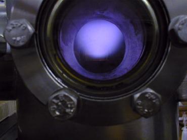
Figure 1.3 Photograph of the microwave plasma discharge used for the work in this thesis. (Reactant gases: 1% CH4/H2).
1.4.3 Plasma Physical Properties
Free electrons gain significant energy from the microwave field, but under the low pressures used in CVD collide (relatively) infrequently with gas molecules. Thus electrons have much higher energies, and hence higher velocities, than neutral and ionic species. Electrons therefore rapidly diffuse from the plasma region, and are lost at the reactor walls, before they can thermalise with neutral and ionic species. Two temperature fields are therefore needed to define the temperature of a microwave plasma. These are the electron temperature Te, and the neutral gas temperature Tg. Thus Te>Tg in the plasma, demonstrating that the system is not in thermal equilibrium. Electron temperatures have been measured using Langmuir probe techniques or calculated using computer models, and are found to be in the region of 1-20 eV (104 to 105 K) for typical diamond depositing plasmas [[46],[47]]. The neutral gas temperature is believed to be in the range 800-5000 K (0.07-0.4 eV), depending on the experimental conditions [46], demonstrating the thermal non-equilibrium of the electrons and neutrals. Ions cannot respond to the rapidly oscillating microwave field as quickly as electrons due to their greater mass. Ions thus have similar energies to neutral species, as they collide with the neutrals and thermalise.
1.4.4 ASTeX-type Microwave Plasma CVD Reactor
Unfortunately, in the NIRIM-type reactor, the substrate temperature cannot be independently controlled from the plasma parameters as the substrate is immersed in the plasma. One solution to this problem is to use an ‘ASTeX’-type reactor design (ASTeX is a commercial manufacturer of plasma systems based in the US). In an ASTeX-type reactor, the plasma can be generated above a substrate, remote from all reactor surfaces. This minimises the effect of plasma heating on the sample, allowing almost independent control of plasma and substrate parameters.
Figure 1.4 Schematic diagram of an ‘ASTeX’-type reactor.
This design uses a microwave generator and rectangular waveguide, with a mode converter to convert the TE10 mode in the rectangular waveguide to a TM01 mode in a cylindrical waveguide (the reactor vessel). A moveable antenna maximises energy coupling between the two waveguide sections. The cylindrical waveguide is terminated by the metallic substrate holder. Microwave engineers would now classify this section as a ‘cylindrical resonant cavity’. As with the waveguide, electromagnetic field modes are supported in the cavity. Further tuning of the microwave circuit is possible by using the moveable substrate heater to adjust the cavity geometry. Generation of the plasma occurs by the same mechanisms as discussed above for the NIRIM-type reactor, in the region(s) where the local electric field strength is highest. The ASTeX-type reactor, or slight variations thereof form the most common microwave plasma CVD reactor types encountered. The microwave reactor used in this thesis is itself a variant on the ASTeX design. In reality, reactors are internally far more complex than simple cylinders due to the presence of service ports, welds, diagnostic probes and so on. In general it is only possible to predict the electromagnetic field structure, and hence plasma location, by numerical solution of Maxwell’s equations within the entire reactor volume, as in the modelling work of Wild et al [[48]].
Figure 1.5 Reactor modelling by Wild et al [48]. The diagram on the left shows the calculated electric field strength in the reactor, while that on the right shows the calculated plasma location. The bar through the centre of the reactor represents the position of the quartz window.
1.5 CVD Diamond Films
Diamond can nowadays be deposited by CVD as a continuous film on a variety of substrate materials. These films are polycrystalline, that is consist of many small diamond crystallites which have fused together in the early stages of growth (see Fig. 1.6).

Figure 1.6: Formation of polycrystalline diamond films. Diamond nuclei (black) formed in the initial stages of growth coalesce as the growth time is increased. The black lines demonstrate the evolution of film morphology with time.
The precise morphology obtained depends on the growth conditions used. Using conventional CH4/H2 reactants, crystals with triangular (111) facets are grown at low CH4:H2 ratios (Fig. 1.7a). As the CH4:H2 ratio is increased, a change to square (100) faceting occurs (Fig. 1.7b). At high CH4:H2 (>1.5%), crystal size decreases and eventually a smooth nanocrystalline film is grown (Fig. 1.7c) [[49]]. In addition, an optimal temperature window for diamond formation exists for substrate temperatures between 750°C and 1100°C. The growth rate of diamond films increases with process pressure in the MWCVD technique [[50]].
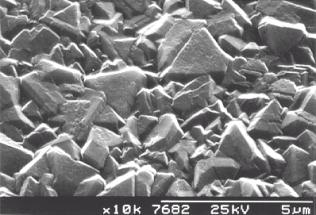
Figure 1.7a Scanning electron microscope image of (111) faceted CVD diamond.
Figure 1.7b Scanning electron microscope image of (100) faceted CVD diamond.

Figure 1.7c Scanning electron microscope image of nanocrystalline CVD diamond.
1.5.1 Growth Rates
Microwave plasma (MW) CVD and hot filament (HF) CVD growth rates are typically in the range 0.1-10 mm h-1, whilst arc-jet and combustion flame synthesis can attain 50-1000 mm h-1. However the areas coated by these techniques are a few cm2 for all techniques except MWCVD, which can coat samples in excess of 20 cm diameter. These figures are improving year by year, and CVD diamond based components are now being manufactured and sold commercially.
1.5.2 Film Quality
The quality of CVD diamond is usually considered in terms of the proportion of sp3-bonded carbon to sp2-bonded carbon in the sample. Diamond is the sp3-bond-hybridised form of carbon, whilst graphite is the sp2-bonded allotrope. Factors such as crystal size and habit, and proportion of other elemental impurities (H, N, Si etc.) incorporated into the film also indicate its quality. The quality of films is generally considered to be best at low input CH4:H2 ratios, but worsens at higher CH4 input. At high substrate temperatures the diamond quality also suffers, graphite being deposited at ~1500 K and above.
1.6 The Substrate Material
The relatively high temperature conditions used in CVD diamond synthesis mean that only a small range of materials may be coated at present. Mainly refractory materials such as W, Mo, Si etc. have been used as substrate materials. It is not yet possible to coat low temperature materials such as GaAs, Al, glasses, and plastics with CVD diamond, however low temperature growth is an important goal of CVD diamond research. Materials which form a carbide are found to support diamond growth. However, materials such as Fe and steel possess a high mutual solubility with carbon, and only graphitic deposits or iron carbide result during CVD growth on these materials. For applications where the substrate needs to remain attached to the CVD diamond film, it is necessary to choose a substrate which has a similar thermal expansivity to diamond. If this is not done the stress caused by the different rates of contraction on cooling after deposition will cause the film to delaminate from the substrate.
1.7 Nucleation Processes
In order for continuous film growth to occur, a sufficient density of crystallites must be formed in the early stages of growth. In general, substrates must undergo a nucleation enhancing pre-treatment to allow this. This is particularly true for Si wafer substrates which have been specially polished to be smooth enough for micro-electronic applications. Substrates may be pre-treated by a variety of methods such as:
· Abrasion with small (~mm sized) hard grits (e.g. diamond, silicon carbide).
· Ultrasonication of samples in a slurry of hard grit.
· Deposition of hydrocarbon/oil coatings - even ball point pen ink! [[51]].
The basis for most of these methods is to produce scratches which provide many sites for nucleation. It is also possible that small (~nm sized) flakes of diamond, produced during abrasion with diamond grit, become embedded in the substrate, and that CVD diamond grows on this material [[52]]. Evidence for homogenous nucleation of diamond in the gas phase has also been presented, however this is not believed to be the dominant process when, for example, manual abrasion is used [[53]].
It would be desirable to produce nucleation sites without damage to the underlying substrate. This is particularly important for some applications such as diamond electronics and optical components. One method for encouraging nucleation without damaging the substrate material has been developed: bias enhanced nucleation (BEN) [[54],[55]]. This process is however still relatively new and, as an aside, we have attempted a small amount of work on BEN which is presented in appendix B, where an explanation of this technique can be found.
1.8 Characterisation of Diamond CVD
The boom in CVD
diamond research has led to many different areas of expertise being developed
around the world. Characterisation of
the deposited films by electron microscopy and Raman spectroscopy form the most
widely used CVD diagnostic techniques (Chapter 2). Many successful CVD diamond growth ‘recipes’ have been
found by trial and error techniques of growing films until the film properties
match those required for a given application.
However, such an approach gives us only limited insight into the mechanism of CVD diamond growth. CVD is a complex process, and can be broken
down to three main parts, as in the diagram of Butler and Woodin (Fig. 1.8) [[56]].

Figure 1.8 The three main processes occurring to the input gases during CVD diamond growth: Activation, Species Transport, and Surface Chemistry (adapted from [56]).
Initially reactant gases are activated (e.g. by hot filament, plasma) and gas phase chemistry and physics play roles in forming reactive species. Secondly, species which pass through the activation zone are transported to the substrate. The nature of the transport mechanism depends on the gas pressure and flow rate employed, and may be diffusional (HF and MWCVD) or convective (plasma jet, combustion flame) [56]. Thirdly, processes occur at the substrate surface leading to the net incorporation of carbon in the growing diamond surface. These processes depend on the type of substrate, its temperature, and the flux of species incident at the surface, and they determine the morphology and quality of the diamond film.
In addition to growth experiments, many studies have attempted to deal with the three parts of the CVD process (outlined above) in isolation. Particularly relevant to the present work are studies of the gas phase chemistry carried out for MW and HF CVD. It is convenient to discuss the findings of hot filament gas phase studies first, as much of this research has relevance to the studies of the gas phase during MWCVD, considered in Section 1.10.
1.9 Studies of HFCVD Gas Phase Chemistry
It is evident from Fig. 1.8 that gas phase chemistry plays a pivotal role in deciding whether diamond formation will occur. Many different techniques have been used to probe the gas phase composition and chemistry during CVD. Most of these techniques have been used exclusively to study HFCVD.
1.9.1 Early Studies
The first in situ hydrocarbon concentration measurements during HFCVD were made using infrared diode laser absorption spectroscopy, where it was found that 10-20% of the input 0.5% CH4 in H2 was converted into C2H2, indicating that significant chemistry involving radical species must be occurring [[57]]. Resonance enhanced multiphoton ionisation (REMPI) has been used to detect, and study the radical species H [[58]] and CH3 [[59],[60]]. H atoms were found to be most abundant at the hot filament surface, where they are believed to be formed during HFCVD. The concentration of CH3 was found to be highest a few millimetres from the filament. CH3 concentrations have also been determined by cavity ringdown spectroscopy (CRDS) [[61]] and agree with those found by REMPI. Laser induced fluorescence (LIF) has been used to study H during HFCVD [[62]] and concentrations of the order of ~1015 cm-3 were found, again in good agreement with the REMPI data [58]. Gas chromatography [[63],[64]], and mass spectrometry [[65],[66]] have been used to study bulk stable species using sample extraction probes positioned at the substrate level. CH4 and C2H2 were the dominant hydrocarbon species, with small amounts of C2H4 and C2H6. The probe design was such that reactive species were destroyed during sampling; only stable molecules could be detected.
1.9.2 Molecular Beam Mass Spectrometry
An improvement to the mass spectrometric methods was made by Hsu et al who applied the technique of molecular beam mass spectrometry (MBMS) to the hot filament system [[67]-[69]] This technique allows simultaneous in situ detection of stable and radical species from the gas phase, overcoming many limitations of the techniques discussed above.
Figure 1.9 Schematic diagram of a molecular beam mass spectrometer. P refers to the pressure in each section of the system, with P0>>P1>P2.
The gas sample is extracted directly from the region of interest through a ‘small’ sampling orifice. A large pressure differential (>20000 times) is maintained across the orifice, with the region behind the orifice being the low pressure side. This causes gas entering the low pressure region to form a continuous supersonic expansion [[70],[71]]. As gas molecules travel away from the orifice in the expansion, their local number density, and hence collision frequency, decrease very rapidly. Collisions become negligible as molecules enter free molecular flow a few orifice diameters downstream of the orifice [69,70]. Chemical identity of species in the expanded gas is unchanged from that in the sampling region if the system is designed to make the time spent in the gas expansion by a typical molecule much shorter than the timescale on which that particular species is lost by reaction (e.g. radical recombination). For example, one of the fastest reactions occurring during diamond CVD is the following:
H2 + CH3 ® H + CH4 Reaction 1.1
Hsu was able to show that for Reaction 1.1 the time spent in the expansion by a typical CH3 radical before transition to free molecular flow is ~1 ms, whereas the timescale for destruction of CH3 in the gas phase is ~286 ms for a 1% CH4/H2 gas mixture at 20 Torr [69].
By making the orifice as short as possible, reactions on the inside wall of the orifice can be minimised. The expanded (collisionless) gas is collimated by a skimmer orifice to form a molecular beam which passes into the mass spectrometer stage, where it is detected. In the experiments of Hsu et al three stages of differential pumping were required to lower the pressure in stages from 20 Torr (CVD reactor) to 10-7 Torr or less, where the mass spectrometer could be operated.
Figure 1.10 Schematic diagram of Hsu’s experiment. Adapted from [68].
In Hsu’s experiments the molecular beam mass spectrometer was positioned inside the substrate holder. This allowed the composition of the flux incident at the growing diamond surface to be determined. Hsu was able to determine simultaneously the concentration of stable hydrocarbon species, and the radical species CH3 and H at the substrate surface. The disadvantage of this sampling position is that the effects of gas phase chemistry are combined with surface chemical, and gas transport effects. Other researchers, notably here at Bristol, have used MBMS sampling to study the gas phase chemistry in isolation [[72]-[77]]. This was facilitated by using a conical probe with a small tip to sample directly from the activation zone.
1.9.3 Summary of early HFCVD gas phase composition
studies
A summary of the results of these various investigations may be given. For small hydrocarbon concentrations in H2 (<1%), chemical reactions in the activation zone form a mixture of species whose composition depends only on the input C:H ratio in the feed gas. However, at high input hydrocarbon concentrations the input hydrocarbon was found to be the most prevalent moiety, and this was attributed to hydrocarbon saturation of the filament surface available for dissociation of H2 [[78]]. With fewer H radicals being created at the filament surface to drive the gas phase chemistry, the input hydrocarbon remains largely unreacted. The saturation of the filament surface by hydrocarbon species, preventing H2 dissociation has been termed filament poisoning.
1.9.4 The Role of Radical species
The importance of radical species in diamond CVD appears to be manifold. Firstly large quantities of H atoms are produced in the gas activation process. These react with hydrocarbon species to produce hydrocarbon radicals (CxHy) which may be responsible for growth at the substrate surface. At the low pressures used in CVD diamond growth, H atom recombination in the gas phase is slow, and thus the amount of H produced exceeds the thermodynamic equilibrium concentration, making radical chemistry important in the gas phase. At the surface, H is known to preferentially remove graphite rather than diamond [16,17]. Under conditions of CVD diamond growth, the diamond surface is almost entirely H-terminated. Hydrogen abstraction reactions by atomic H create ‘dangling bonds’ at the surface which are good candidate sites for carbon addition to the growing diamond lattice. If all the H atoms were removed (such as by heating under UHV), the surface layers would reconstruct to a graphitic sp2-bonded configuration. Thus H atoms are vital for the stability of the diamond surface in the CVD pressure and temperature regime where diamond is not the stable carbon phase.
1.9.5 Temperature Effects
In addition to species’ identities and concentrations, the spatial temperature profile needs to be known for a complete description of the gas phase. Typically in HFCVD, the filament is heated to 2600 K, and a temperature of 900°C is maintained at the substrate ~5 mm from the filament. Experimentally, large temperature drops are found at the filament-gas and gas-substrate interfaces. A fairly slow decrease in gas temperature is observed as one traverses the filament-substrate gap, and the temperature in this region is typically 1400-2000 K [65], see Fig. 1.11.
Figure 1.11 Gas temperature profile measured in a hot filament reactor at 20 Torr by Harris et al (adapted from reference [61]).
An important temperature related effect has been noted by in situ detection methods. In the region of the hot filament the total measured carbon is less than the total input carbon. In the cool regions far from the filament these totals are equal, as expected. It is believed that such observations are the result of thermal diffusion (Soret effect) [60,64,66,[79]]. In the presence of a significant temperature gradient, mass dependent diffusion effects occur, whereby heavier species preferentially diffuse away from hot regions. This explains the underabundance of heavy (i.e. hydrocarbon) species in the high temperature region close to the filament, compared with the lighter components (i.e. H2, H).
Fig. 1.12 MBMS results of Tsang, showing the effect of thermal diffusion on species concentration measurements during HFCVD. The total measured carbon is less than the 1% CH4 input at elevated temperatures (adapted from [76]).
1.9.6 The Diamond Growth Species
From the collected data, two main species have been put forward as possible diamond growth species. These are acetylene, C2H2 [[80]], and the methyl radical, CH3 [[81]]. Isotopic labelling studies have produced strong evidence that CH3 is the primary diamond growth species under typical HFCVD growth conditions by detecting the proportion of 13C in gas phase CH4 and C2H2 using matrix isolation infrared absorption spectroscopy [[82]]. The measured isotopic fraction in the films was similar to the estimated gas phase CH3 isotope ratio and significantly different from the measured C2H2 ratio. The results of Johnson et al indicate that the same appears to be true in a microwave plasma environment [[83]]. It has also been shown that under ultra-high vacuum (UHV) conditions, diamond crystals can be grown using the simultaneous application of supersonic free jets of H and CH3 [[84]]. Substituting C2H2 for the CH3 jet produced only graphitic deposits.
Since the hot filament system is simpler and cheaper to build than other deposition systems, the wide range of techniques used to study HFCVD can be seen as paving the way for application to other, less studied, deposition systems such as MWCVD.
1.10 Studies of Microwave Plasma Chemistry
The gas phase of the microwave plasma system remains poorly studied by almost all diagnostic techniques. This is surprising as MWCVD is the technique of choice for the commercial growth of large area, high quality, diamond films [[85]]. The consensus view is that the gas phase chemistry during MWCVD is not very different from that encountered during HFCVD [56] - indeed the two techniques operate under similar conditions, producing films with comparable quality and growth rate [56]. This is a reasonable assumption to make, however the plasma must contain electrons and ionic species which will provide extra chemical reactions not available in the hot filament system. The assumption that microwave plasma chemistry is similar to that encountered during HFCVD will be explored in this section.
1.10.1 Optical Emission Spectroscopy studies
As the plasma is luminous, it is possible to identify some plasma species by examining the light they emit. Optical emission spectroscopy (OES), as this technique is known has been used to show the existence of H, C2, and CH species in a CH4/H2 plasma [[86]]. C, CO, OH, and H2 were additionally detected in CH4/H2/O2 plasmas [[87]]. Mitsuda et al related the presence of H, C2, and CH to the quality of the grown film [[88]]. Intense C2 emission, relative to CH, was found to lead to poor quality deposits. Muranaka et al [[89]] found that C2 and C emission was suppressed when ground state H was present in the gas phase (e.g. by adding H2 to a CO/He plasma). Excited state H was considered responsible for the formation of amorphous hydrogenated carbon (a-C:H) by reaction with graphitic carbon.
1.10.2 Actinometry
It is not possible to determine species concentrations using OES unless a quantity of inert gas is added to the feed as an actinometer. Using Ar as an actinometer, it is possible to measure the relative ground state concentration of H. Barshilia et al used this technique to determine that the H concentration, [H], in a 1% CH4/H2 microwave plasma increases with pressure [[90]]. By making further approximations, a quantitative estimate of [H] ~8´1016 cm-3 (a mole fraction of 0.4 assuming a gas temperature of 2000 K and ideal gas law behaviour) at 40 Torr was made. Sánchez et al found an H atom mole fraction of 0.06, also using actinometry under similar conditions [[91]].
1.10.3 Fourier Transform Infra-Red Spectroscopy
studies
Mitomo et al used Fourier Transform Infra-Red spectroscopy (FTIR) to measure stable species concentrations in C/H and C/H/O containing microwave plasmas [[92]]. They found that as the input CH4 concentration, [CH4] is increased in a CH4/H2 feed, the measured C2H2 concentration, [C2H2] increases markedly, while the measured [CH4] plateaus, or even decreases (Fig. 1.13). The results for other C/H containing gas mixtures revealed similar concentrations and species behaviour to the CH4/H2 system. These trends mimic those seen previously in the hot filament system, except the filament poisoning effect is absent as activation occurs throughout the plasma region. This represents a fundamental difference between HFCVD and MWCVD.

Fig. 1.13 FTIR measurements of stable species concentrations in a CH4/H2 microwave plasma at 30 Torr (adapted from [92]).
1.10.4 Mass Spectrometry studies
Weimer et al used a quartz sampling probe to extract gas from the region adjacent to a diamond depositing microwave plasma [[93]]. Mass spectrometry was employed to detect stable species using CH4/H2, and CH4/H2/O2 feeds. When using low concentrations of carbon containing gases in H2 carbon was present mainly in the form of CH4, with less C2H2, in agreement with the results of Mitomo et al [92]. The addition of O2 to the feed depleted the amounts of CH4 and C2H2, promoting the formation of CO and H2O. Weimer et al also used a shielded thermocouple to determine a maximum gas temperature of 1100 K in a 170 W discharge [93].
1.10.5 Absorption Spectroscopy studies
Erickson et al measured a CH3 column density of 6´1013 cm-3 in a 1% CH4/H2 microwave plasma using a high sensitivity absorption spectrometer [[94]]. This is the same value as that 4 mm from the filament during HFCVD [61], and shows that the most prevalent radical species (and the favoured growth species) is present at similar concentrations in both systems. Erickson et al also placed an upper limit of 1010 cm-3 on the CH radical concentration, giving an upper bound to the hydrogen dissociation ratio [H]/[H2] £ 0.008. Using H2 emission spectroscopy, the gas temperature was found to be (1200±100) K throughout the plasma, in agreement with Weimer et al [93].
1.10.6 MBMS studies
MBMS has also been applied to MWCVD. Hsu extended his MBMS work on the hot filament system by studying MWCVD in the same reactor [[95],[96]]. He was able to show that the gas composition close to the substrate was not very different from that found previously during HFCVD. Computer modelling using the Sandia National Laboratories CHEMKIN code [[97]] was also attempted. To date, computer models have been far more prevalent than experimental studies of the microwave plasma environment. These models have the drawback of requiring many assumptions to be made (such as gas temperature, and electron energy distributions) which are not well known. Only in the work of Hsu and McMaster [95] have these models been compared with species concentrations measured experimentally (by MBMS). It was found that although the species concentrations were not dissimilar to those found during HFCVD, a numerical model based only on neutral-neutral gas phase chemistry was not adequate to simulate the experimental results. C2H2, CH3, and H were in good agreement with experiment, however the model predicted too little CH4, too much C2H4 and the existence of C2H6, which was not detected under any experimental conditions.
1.11 Summary
In summary, no one gas phase diagnostic, except MBMS, can provide absolute concentration measurements of all species of interest at one point in the CVD reactor. The chemistry during MWCVD appears to be similar to that found during HFCVD, however thermal chemistry is insufficient to model the experimental results. The number of publications relating to MWCVD gas phase chemistry is small compared with the work done on the hot filament system. More studies of the gas phase chemistry during MWCVD are required and the remainder of this thesis will hopefully help to partially redress this imbalance.
1.12 References