The Development of LEP Technology
The first LEPs were not particular applicable as a display technology. PPV was initially produced with only 0.01% quantum efficiency and a voltage threshold of 14V and with a likelihood of exciton decay leading to photon emission of only 8% (with a theoretical maximum of 25%). If LEPs were to find a foothold as a display technology they would have to be far more efficient and operate at lower voltages in order to make them preferable to current technologies such as CRT and LCD.
Injection barriers
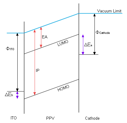
Electrons injected by the cathode enter the LEP's conduction band from the cathode's HOMO. Consequently there is a barrier to entry corresponding to the difference between these two energy levels. The same is true of the anode and the LEP's HOMO. This situation is illustrated in figure 1, using PPV as an example.

| ΔEe | Injection barrier for electrons. |
| ΔEh | Injection barrier for holes. |
| ΦCathode | Work function for the cathode. |
| ΦITO | Work function for ITO (the anode). |
| IP | Ionisation potential of PPV. |
| EA | Electron affinity of PPV. |
Larger barriers result in higher voltage requirements and less quantum efficiency. Aluminium was originally used as the cathode. Aluminium has a large work function, much larger than the electron affinity (EA) of PPV, and as shown by figure 1, a large difference in these energies gives a large injection barrier. Using lower work function metals such as calcium have allowed CDT to develop lower voltage LEPs.
Indium-tin oxide (ITO) is similar to the indium oxide originally used as the anode. It's main advantage is that it is optically transparent so that photons resulting from recombination within the polymer can exit the diode. It also has a work function remarkably close to the ionisation potential (IP) of PPV, which results in a very low injection barrier (0.2eV).
Carrier Confinement
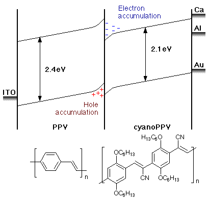
Modification of PPV can alter it's band gap. It was found that creating a diode (exp link) that contained a layer of PPV and a layer of modified PPV could improve efficiency. Figure 2 shows a PLED that consists of PPV and cyanoPPV (sometimes written CN-PPV, view Chime), CDT labs reported that a quantum efficiency of 2.5% could be obtained, leagues ahead of the first reported values.

The use of cyanoPPV is beneficial two-fold. Firstly, carrier-confinement occurs at the polymer/polymer interface due to the polymer/polymer injection barrier, as a consequence when electrons or holes surmount the barrier and cross polymer, recombination is much more likely due to the build up of charge density. Secondly, efficiency is improved because the injection barrier between the cathode and cyanoPPV is lowered.
Current Design
LEP development has led to the fundamental PLED design shown in figure 3.

Here, the hole-conduction layer can be an LEP, as in the cyanoPPV example. A reflective cathode is preferable as light is only desired from the PLED's front, metal cathodes fulfil this role.
Alternative LEPs include other conjugated polymers such as polyfluorene, which is the preferred polyarylene.
Colours
Manipulation of the side-groups on PPV has led to production of other colours. Red, yellow and blue LEPs have also been made. Red, green and blue emission is required to make full-colour screens.
Learn about the future of LEPs..