Chapter 7 : Cavity Ring Down Spectroscopy
studies of C2 in a
DC-arcjet reactor
Previous gas-phase studies of microwave plasma enhanced
diamond deposition have concluded, that the dicarbon (C2) species
concentration may be inversely proportional to the diamond film quality[1]. In contrast, optical emission studies of a
DC-arcjet diamond CVD reactor operating on Ar / H2 / CH4
gas mixtures, have found that high C2 concentration correlates with
high quality diamond growth[2].
Following on from the results gained from OES studies
(chapter 6), together with reports from other groups[3]
suggesting C2 may be the principle growth species in DC-arcjet CVD
deposition, further accurate studies of C2 in the gas-phase
environment were required. The method
of choice was cavity ring down spectroscopy (CRDS) which, as described in
Appendix 3, is a highly sensitive line-of-sight absorption technique. This technique was chosen in preference to
other diagnostic methods for a number of reasons.
Primarily, CRDS yields absolute absorbance and therefore
absolute species number densities. CRDS
being an absorbance based diagnostic is not influenced by collisional
quenching, a fundamental problem with OES measurements. The use of CRDS to probe low-lying excited
states also avoids problems encountered by interpreting OES measurements due to
the nonequilibrium nature of the plume.
Luque et al.[4]
previously used Laser Induced Fluorescence (LIF) to study both C2(a)
and CH(C2P) radicals in a 1.6 kW DC-arcjet reactor. However, LIF studies rely on the collection
and interpretation of the induced fluorescence, it will therefore be subject to
collisional quenching of the induced upper state. The LIF study concluded that the C2 concentration was
too low
(~3.1 ´ 1010 cm-3) to account for the high
growth rates observed. Recent growth
simulations have demonstrated the feasibility of C2(C) insertion into
C-H bonds at hydrogen terminated surfaces and addition to a
clean (110) diamond surface[5].
This chapter aims to describe and discuss the experimental
set-up and results of a CRDS study of C2(a) in a DC-arcjet
reactor. The results shown are compared
to previous OES studies of the C2 (d-a) transition.
7.1
Experimental Set-up
The torch-head arrangement is identical to that used in previous studies described in chapter 6, however, changes to the chamber set-up have been implemented to allow an optical cavity to be established. The changes to the chamber are shown schematically in figure 7.1, where the cavity is defined by two highly-reflective mirrors positioned a fixed distance apart (101 cm) in the same horizontal plane.
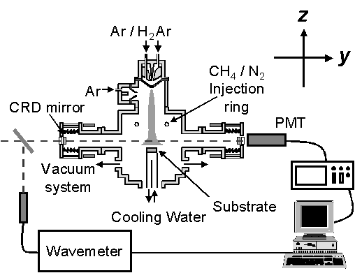
Figure 7.1 Schematic of the
experimental set-up used in the CRDS study.
Light from a Spectra Physics PDL-3 dye laser, pumped by a Spectra Physics DCR 2A Nd-YAG laser, operating at 10 Hz, was passed, by way of a number of defining and manipulating optics, into the chamber via one of the cavity ring-down mirrors. The general set up for the laser, cavity and signal collection is outlined in figure 7.2.
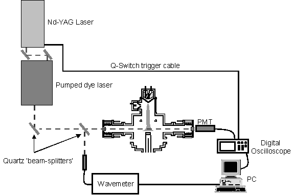
Figure
7.2 Schematic outline of the experiment
showing the apparatus used for laser propagation, cavity definition and signal
collection. Note the diagram is not to
scale.
The light, once passed into the chamber, is reflected on the
inner surfaces of highly reflective mirrors (~99.93% at 515 nm) which defines the cavity with a typical
non-absorbing 1/e ring down time of ~4.8 ms. Light escaping
from the cavity via the exit mirror is detected by a photomultiplier tube
(PMT), with prior attenuation by optical filters. The mirror mounts are the same design as those previously used in
CRDS studies of the Hot filament CVD environment[6]
and each comprise of four micrometers allowing accurate and stable definition
of the optical cavity.
Operation of the reactor, and thus heating of the chamber
walls, mirrors and cavity arms, did not discernibly effect the non-absorbance
ring-down time. The light exiting the
cavity is collected by the PMT with the signal transferred to a digital
oscilloscope (LeCroy 9361) that is triggered from the Q-switch trigger provided
by the Nd-YAG laser. Operating on a
fraction of the incoming laser light, the frequency of the exiting light is
constantly measured by a wavemeter (Coherent Wavemaster). Both the output channels from the
oscilloscope (via a GPIB interface) and the frequency output from the wavemeter
were transferred to a PC for analysis and storage.
Determination of the C2(a) absorption is carried
out via interpretation of changes in the ring-down rate coefficient. A PC, using DRIVE, carried out analysis of
the time-gated ring-down transients, together with fitting to an exponential
growth function. The change between the
on- and off- absorbent ring-down fit, is represented by an exponential
coefficient, Dk.
7.2 CRDS of C2
The C2 spectrum, presented in figure 7.3 (upper
trace), was recorded 20 mm from the substrate surface and 142 mm from the
N-torch nozzle. This is a section of
the absorption d3Pg (n’=0) ¬ a3Pu (n’’=0) transition (C2
Swan Band system), background-corrected via subtraction of a non-absorbent
frequency scan, to remove the rising absorption baseline.
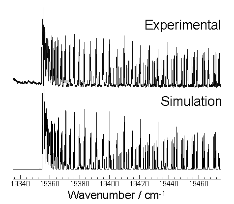
Figure 7.3
Section of the background-corrected absorption spectrum for the C2
d3Pg ¬ a3Pu
(0,0) transition (upper trace) together with a simulation (lower trace). The spectrum was recorded at z = 20 mm (where z = 0 mm defines
the substrate surface) using typical high quality growth conditions (Chamber pressure = 50 Torr, Input CH4
= 3.3% of the total H2 flow,
Input power = 6.5 kW).
The simulation (lower trace) was calculated using the
simulation program PGOPHER[7],
operating on the rotational constants tabulated in table 7.1.
Parameter
|
a3Pu (v=0) |
(d3Pg) – (a3Pu) |
|
T |
0.0 |
19378.46456 |
|
B |
1.624075 |
0.1215293 |
|
D ´ 106 |
6.479 |
0.3760 |
|
AD ´ 104 |
2.76 |
2.66 |
|
A |
-15.2696 |
1.2691 |
|
H ´1012 |
7.85 |
-7.85 |
|
o + p + q |
0.67726 |
-0.06460 |
|
p + 2q ´ 103 |
1.408 |
1.010 |
|
q ´ 104 |
-4.97 |
-2.666 |
|
oD + pD + qD
´
106 |
-8.122 |
8.122 |
|
pD + 2qD ´ 108 |
9.42 |
-0.942 |
|
qD ´ 108 |
-1.288 |
2.49 |
|
l |
-0.1476 |
0.1786 |
Table 7.1 Table of rotational constants used to
simulate the C2 d3Pg (n’=0) ¬ a3Pu (n’’=0)
transition shown above. The table shows
the molecular constants (in cm-1) for the a3Pu state of C2 and the differences
between the upper d3Pg state
and lower a3Pu state
and are reproduced from reference [8].
The rotational temperature of the trial simulation was fixed
at 2400 K. Due to CRDS being an
absorption (and thus non-species specific) technique it is essential to ensure
that C2 is being detected.
From the comparison of the spectrum and simulation, it is clear that
within the wavelength range scanned C2 is the absorbing
species. Being an absorption-based
technique CRDS is capable of obtaining absolute species concentrations. In this study of the C2 d3Pg (n’=0) ¬ a3Pu (n’’=0) transition the
absolute number density of the a- state C2 (v=0) (herein C2(a))
will be measured.
7.2.1 C2
rotational temperature determination
The spectrum obtained illustrates the high C2
rotational temperatures reached in the dc-arcjet environment, with populations
extending into highly excited rotational states (N’’ > 40), however,
recent extended C2 frequency scans6 have shown rotational
lines at N’’ > 67. In order
to obtain a rotational temperature from the spectrum, a Boltzmann plot approach
has been used.
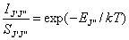
This method relates the measured C2 line
intensities, IJ’,J’’, together with absorption line strengths, SJ’,J’’, calculated
from the PGOPHER simulation with the rotational energy in the a3Pu state, EJ’’. Assuming that a
thermal equilibrium exists, an adapted version of the Boltzmann equation may be
used to describe the population of the rotational states, such that,
 Equation
7.1
Equation
7.1
where IJ’J’’ is the
integrated line intensity, SJ’J’’ corresponds
to the line strength factor, k
the Boltzmann constant and T the gas
temperature. By plotting ln(IJ’,J’’/ SJ’,J’’) against EJ’’/k for a number of
measured rotational lines an estimate of the local gas temperature may be
obtained. Figure 7.4 shows the
Boltzmann plot produced from the measured line intensities, calculated line
strengths and rotational term values (divided by k), the gradient of which is 1/T.
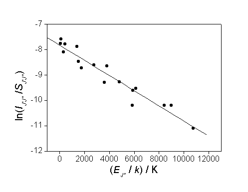
Figure 7.4
Boltzmann plot composed from the measured C2(a) rotational
line intensities and the calculated line strengths (from PGOPHER). The measured line intensities were obtained
from the frequency scan shown in figure 7.3 with process conditions detailed
therein. By obtaining a best-fit to the
data-sets a linear relationship is shown with a gradient (= 1/T)
yielding the rotational temperature of the gas.
From the gradient of the best-fit line a rotational
temperature of 3300 ± 200 K was obtained for the C2(a) radicals. However, as previously seen in spatially
resolved OES measurements of C2, the plume is not homogenous. This inhomogeneity relates to both the local
gas temperature and species concentrations, with the maximum of both being in
the axial centre of the plume. CRDS,
being a line-of-sight measurement, samples a column of C2 radicals
at both relatively high and low local gas temperatures therefore yielding an
average column temperature. As
previously shown in Abel-inverted spatially resolved OES measurements of the C2
(d-a) transition, the abundance of C2 (a) species will be
centred about the hotter central core of the plume (Figure 7.5).
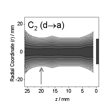
Figure 7.5
Reproduction of figure 6.6a showing the Abel-inverted spatially resolved
emission from the C2 (d-a) transition. The C2 emission density map, shown here with a
logarithmic grey scale, identifies a maximum in emission in the central core of
the plume. CRDS measurements of the C2
(a) state were taken in a column 20 mm from the substrate surface as
shown on the figure (arrow).
The measured rotational C2 temperature determined
by CRDS is comparable to that of C2 (d-a) rotational and vibrational
optical emission. Previous
investigations[9]
concentrating on C2 Swan band emission and comparison with PGOPHER
simulations of the (0,0) and (1,1) transitions were consistent with rotational
and vibrational temperatures of ~3300 K.
This high level of agreement indicates that rotational
temperature determination by analysis of OES from the C2 (d-a)
transition is reliable. This also goes
some way to support the postulate that electron impact excitation of C2
to the d3Pg state (and its measured decay to the a3Pu state)
results in a move towards thermal equilibrium[10]. This underlines the usefulness of fitting to
the C2 OES rotational band contour, and hence determining an overall
local gas temperature.
7.2.2 Determination
of C2 absolute column densities
Being an absorption-based technique, CRDS relies on the
absorption coefficient, a, which is
related to the ring-down time via the equation,
 Equation
7.2
Equation
7.2
where L is the CRDS mirror
separation, c is the speed of light, ![]() is the effective
absorption length of the column containing C2(a) radicals and Dk is the difference in ring-down rate coefficients between
on- and off- spectral absorption lines.
The effective absorption length of the C2 (a) column has to
be estimated from previous spatially resolved OES measurements as the present
CRDS measurements are fixed. From the
Abel-inverted spatially resolved C2 (d-a) OES measurements, it was
found that >95% of the C2 emission emanated from within 0.5 cm of
the plume axial centre. This
effectively gives a
is the effective
absorption length of the column containing C2(a) radicals and Dk is the difference in ring-down rate coefficients between
on- and off- spectral absorption lines.
The effective absorption length of the C2 (a) column has to
be estimated from previous spatially resolved OES measurements as the present
CRDS measurements are fixed. From the
Abel-inverted spatially resolved C2 (d-a) OES measurements, it was
found that >95% of the C2 emission emanated from within 0.5 cm of
the plume axial centre. This
effectively gives a ![]() value of 1 cm. In order to ascertain the fraction, p, of the total (0,0) band oscillator strength that is
associated with each measured rotational line, simulations of the C2(d-a)
(0,0) band were carried out with a rotational temperature of 3300 K. The calculation of p in this manner takes
into account a Boltzmann distribution of the rotational line populations.
value of 1 cm. In order to ascertain the fraction, p, of the total (0,0) band oscillator strength that is
associated with each measured rotational line, simulations of the C2(d-a)
(0,0) band were carried out with a rotational temperature of 3300 K. The calculation of p in this manner takes
into account a Boltzmann distribution of the rotational line populations.
Given that the C2 column density is related to a, via,
a = sabs[C2], Equation
7.3
where sabs is a function
of p and the oscillator strength of C2 (d-a) (0,0), ¦00, is such that
for each integrated rotational line,
 . Equation
7.4
. Equation
7.4
The electronic degeneracies of the d- and a- states are
represented by gd and ga and l is the wavelength of absorption. The literature value of the Einstein A-coefficient for the (0,0)
band of the C2(d-a) transition is
A00 = 7.21 ± 0.30 ´ 106 s-1 (reference [11])
from which we derive an oscillator strength for the d-a (0,0) band of ¦00 = 0.029 ± 0.001.
In order to ascertain C2 number densities within
the plume as a function of process conditions, it is necessary to obtain a
section of this spectrum that will contain information on the population (and
linewidth) of individual rotationally excited states. Figure 7.6 shows the region used together with the corresponding J’’
values.
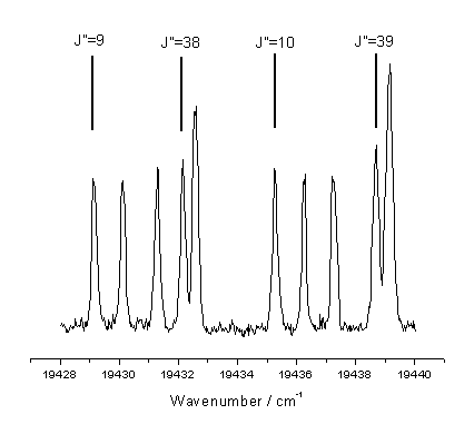
Figure 7.6
Spectral region used to measure C2(a) column densities. The designation of the rotational lines has
been noted in the figure.
This region of the measured spectrum was selected as it
contains lines from both relatively high and low rotational levels spanning J’’
= 9-11 and
J’’ = 38,40 for
the probe transition J’ ¬ J’’.
7.2.3 CRDS measured C2(a) column
densities as a function of process conditions.
By studying the C2(a) column densities obtained
from the rotational lines exhibited in figure 7.6, measurements of the absolute
C2 column density may be obtained as a function of process
conditions. Measurements of the C2(a)
column density as a function of distance from the substrate surface were
carried out using an Ar / H2 / CH4 gas mixture with a CH4
/ H2 ratio of 3.3% (i.e. CH4 flow rate of 60
sccm), chamber pressure of 50 Torr and an input power of 5.6 kW. Figure 7.7 shows the measured C2
column density (cm-3) as a function of distance from the substrate
surface in the range z = 0 to 25 mm from the surface.
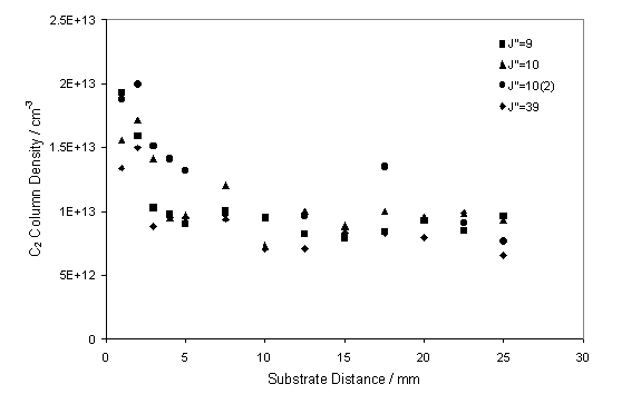
Figure 7.7
CRDS measurements of the C2(a) column density as a function
of distance from the substrate surface.
The measurements shown were obtained assuming a fixed local gas
temperature of 3300 K and an absorption column length of 1 cm.
These measurements were taken by translating the substrate
position relative to the fixed laser beam.
This procedure should be contrasted with spatially resolved OES
measurements, where we translated the viewing column for the emission relative
to the fixed substrate position. The C2(a)
column density close to the substrate surface (within 2 mm) is seen to be
approximately double that observed in the free plume.
It is worth noting that in this study a constant absorption
column length was used which, as figure 7.5 shows, is not applicable close to
the substrate surface. Therefore, the
increase in C2 at the substrate surface may be understood in terms
of an increase in the effective absorption C2 column length, or as
an actual increase in C2.
This observation is in agreement with the OES studies of the C2(d-a)
transition, the apparent increase in C2 at the substrate surface
shown by both techniques may be explained in terms of local gas heating and
‘fanning’ of the plume at the substrate.
Previous OES[12]
and LIF4 studies in DC-arcjet systems have identified a maximum in
gas temperature close to the substrate and attributed this to the presence of a
reflected shock wave from the substrate, due to the incidence of high velocity
gas. Spatially resolved OES
measurements of the C2(d-a) transition2 also showed an
increase in the radial distribution close to the substrate, which will have a
consequence on the CRDS absorption length of the absorbing C2. Future CRDS studies will attempt to measure
the x-axis dependence of C2 to establish which of these two
possibilities is correct.
Clearly from figure 7.7, distances greater than 10 mm from
the substrate surface are representative of the free plume, therefore all
subsequent measurements were obtained from a fixed substrate distance of 20 mm.
The C2(a) column density was measured as a
function of input power between 5.25 and 8.4 kW. Figure 7.8 shows the almost linear increase in measured C2(a)
with input power.
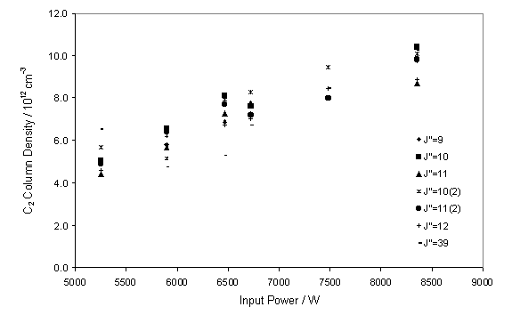
Figure 7.8
CRDS measured C2(a) column density as a function of input
power (W). The measurements were
carried out with a CH4 / H2 flow ratio of 3.3% and
chamber
pressure of 50 Torr.
It is worth noting that the analysis of the C2
column density was carried out assuming a fixed gas temperature. However, it is likely that the local gas
temperature of the probed volume of gas is linked to the input power.
The influence of C2(a) column density on changes
to the input CH4 was also studied.
Previous growth studies have shown that increases in the input power
cause a rise in the growth rate[13]. Figure 7.9 shows the linear relationship
obtained with increasing CH4, such a relationship has previously
been observed from C2(a) LIF studies4.
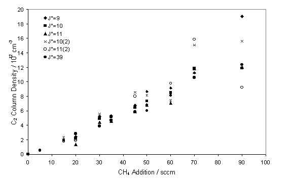
Figure 7.9
C2(a) column density as a function of input CH4. Measurements were taken with a chamber
pressure of 50 Torr and input power of 5.6 kW.
These CRDS studies have provided C2(a) number
densities considerably greater (more than 200 times) than those previously
measured in other DC-arcjet reactors4. However, previous CRDS studies have been carried out on DC-arcjet
reactors operating at significantly lower input powers.
7.3 C2
Gas-phase chemistry
Yu and Girshick14 have proposed a preliminary
gas-phase reaction scheme for thermal plasmas with the C2 production
and loss terms shown in table 7.2. In
this table the forward reaction rate, k,
has been calculated for T = 3300 K,
where k = A exp(-E/RT).
Reaction A / cm-3mol-1s-1 E /
cal mol-1 k / cm-3mol-1s-1
(1) C + CH ¾ C2 + H 2.00E+14 0 2.00E+14
(2) C2
+ M ¾ 2C + M 3.72E+11 139646 2.29E+09
(3) C2
+ H2 + M ¾ C2H2
+ M 1.81E+10 0 1.81E+10
(4) C2H
+ M ¾ C2
+ H + M 3.61E+15 143890 1.90E+13
(5) C2H + H ¾ C2
+ H2 6.03E+05 29106 2.09E+05
Table
7.2 Gas-phase reaction scheme for the
loss and production of C2 in thermal plasmas adapted from reference [14],
where M is a third body. The value of k shown here has been calculated assuming
a gas temperature of 3300 K.
Clearly the dominant gas-phase production route at
temperatures found close to the substrate surface is reaction 1 from table
7.2. Previous computer simulations of
the gas-phase environment have identified that, at typical gas temperatures in
DC-arcjet systems, atomic carbon is by far the most abundant carbon-containing
species. C2 production via
reaction 1 requires the interaction of both C and CH, therefore the reaction
may be considered to be pseudo-first order with respect to CH. This effect may account for the linear
relationship, seen in figure 7.9, between C2 column density and CH4
addition. Simulations in progress with
our colleagues at Moscow State University also point to the need for one or
more additional C2 destruction mechanisms to achieve this
relationship. Amongst these, the
disproportionation reaction,
C2 + C2 ¾ C3 + C Equation 7.1
is likely to be the most important in conditions, as here,
where C2 concentrations are high.
7.4 C2
as a growth species
These studies go some way to investigate C2 in
the gas-phase, however, they do not yield any information on C2 as a
growth species. Experimental and
theoretical studies by Gruen et al.5 have identified C2
as a possible growth species with calculations showing growth onto a (110)
diamond surface being energetically favourable.
The results of this
theoretical study (performed at the AM1 level) indicate that C2 addition to a diamond (110) surface is highly
exothermic with small activation barriers (<5 kcal mol-1). Insertion of C2 into CH bonds on the model surface is energetically favorable, resulting
in an energy lowering of
150-180 kcal per mole of C2.
Formation of single bonds
between adjacent adsorbed C2 units can
be initiated by the addition of a hydrogen atom to one of the adsorbed,
ethylene-like C2 adjuncts. This overall process of joining is
exothermic. It was concluded that the
formation of single bonds between adjacent adsorbed C2 units can also occur directly, without initiation by hydrogen
addition, and is exothermic for the linking of three or more C2 units.
By either pathway, the
formation of a C-C single bond on the surface was calculated to be exothermic
by 40-50 kcal mol-1. This
pathway may go some way to explain why under certain deposition conditions the
(100) growing surface tends to grow quicker than the (111).
7.5 Conclusions
Cavity Ring-down spectroscopic methods have been used to
ascertain C2(a) column densities and a rotational temperature of ~3300 K in a DC-arcjet
operating on an Ar/H2/CH4 gas mixture. This gas temperature is similar to that
deduced from OES studies of the C2 (d-a) transition, and serves to
underline the usefulness of OES, of C2(a), in the determination of
local gas temperature.
The value of OES in the study of the gas environment is also
mirrored in the general trends exhibited as a function of process
condition. Both OES and CRDS identified
an effective increase in C2 close to the substrate surface. However, this could be explained in terms of
an increase in the local gas temperature or by ‘fanning’ of the plume close to
the substrate surface.
The absolute C2 column densities obtained are
considerably greater than those measured via LIF studies of a low power arcjet
reactor by Luque et al., and thus in
the Bristol reactor C2 may well be present in sufficient quantities
to contribute to film deposition. The
CRDS studies described here are the first step in a series that aims to
characterise the gas-phase nature of the plume.
Studies are planned to measure the quantity of CH and C2(C), the latter of
which will have a gas-phase chemistry very different to that exhibited by the
measured C2(a) state. It is
also hoped that computer modelling will reveal further insights of the highly
complex flow and gas-phase environment present in the DC-arcjet system.
References