
Professor Mike Ashfold, email: mike.ashfold@bris.ac.uk
A mass spectrometer consists of an ion source to ionise neutral species, an analyser which separates the ions according to their mass to charge (m/z) ratios, and a detector which, effectively, counts the number of mass filtered ions. There are many ways in which this can be achieved. Most early mass spectrometers employed a magnetic field to deflect ions by an amount proportional to their mass. Others use two DC electric fields to provide two stages of acceleration and then separate according to the ion time-of-flight (TOF). However, most common - at least in plasma processing and most residual gas analysis applications - is the quadrupole mass spectrometer (QMS).
Mass-selectivity in a QMS is achieved using an AC electric field. Consider a three dimensional electric field described by the potential variation
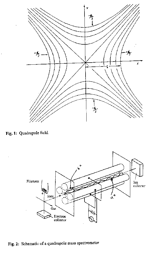
F(x,y,z) =  (1)
(1)
This potential is invariant along the z axis and, for a given value of F0, the equipotentials in the xy plane are four rectangular hyperbolae with asymptotes at 45° to the Cartesian axes, as shown in fig.1. Four symmetrically arranged and precisely parallel cylindrical rod electrodes mounted and biased as shown in fig.2 provide a very good approximation to a potential of this form. Addition of an ionisation source and a detector, one at each end of the z axis of the quadrupole field, constitutes the basis of a QMS.
Consider the motion of an ion (with mass m and charge z) in an electric field of the form defined by eq.1. The problem is separable, and leads to three independent differential equations:
![]() +
+  F0x = 0 (2)
![]() -
-  F0y = 0 (3)
and ![]() = 0.
(4)
= 0.
(4)
The last of these is straightforward: there is no acceleration along the z axis and so the axial velocity is constant. The motion in the x and y directions depends on the time dependence of F0. Quadrupole mass spectrometers operate with a superposition of DC and AC voltages, i.e.
F0= U - Vcos(2pnt). (5)
Opposite pairs of electrodes are connected electrically, and n is usually a radio frequency. Numerical integration of eqs.(2)-(4), with F0as in eq.(5), yields complicated trajectories the details of which depend on the chosen values for r0, n, U and V. Fig.3 shows representative trajectories for m/z 27, 28 and 29.
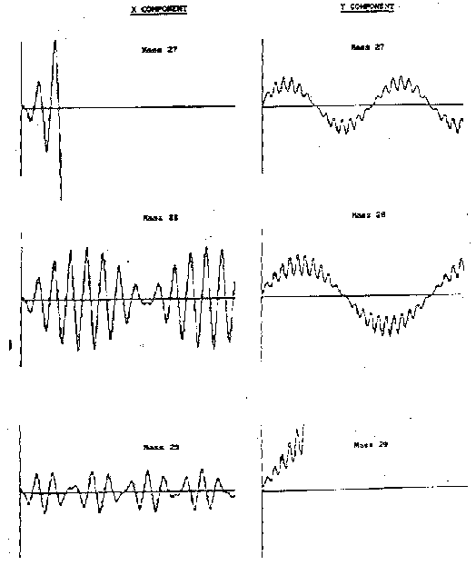
Fig. 3: Representative trajectories for ions with m/z 27, 28 and 29 for = 2 MHz and r0= 2.75 mm.
As these demonstrate, an ion with appropriate m/z ratio (28 in this case) will oscillate symmetrically and continuously about the central axis and pass cleanly through the entire length of the quadrupole and emerge to be detected (ion a+ in fig.2). However all ions with lighter (or heavier) m/z ratio will suffer unstable motion which forces their trajectories to deviate from the central axis in the x (or y) direction where they will strike the appropriate electrode and be neutralised (ions b+ in fig.2). Mass selection is thus achieved by varying V and U (whilst maintaining a constant V/U ratio), or by varying the RF frequency . As the ions emerge from the region bounded by the four rods they are accelerated by a high negative voltage towards the detector (e.g. a channel electron multiplier). A mass spectrum is simply a plot of this detector output as a function of m/z.
A couple of practical details merit further consideration.
Ionisation of the neutral species of interest is normally achieved by electron impact. The electrons are produced by thermionic emission from a hot filament (usually tungsten or thoriated iridium) and accelerated typically to 70 eV, an energy which corresponds to a maximum in the ionisation efficiency curve for most atoms and molecules. However, the quantitative interpretation of mass spectra obtained in this way is complicated by the fact that this energy is more than sufficient not just to ionise the species of interest but also to cause dissociative ionisation.
Consider, for example, mass spectrometric analysis of the gases involved in Si etching using an RF discharge in a CF4/8% O2 gas mixture. F+ ions (m/z 19) can arise both from electron impact ionisation of F atoms in the discharge,
F + e ![]() F+ + 2e
F+ + 2e
and by dissociative ionisation of the (more plentiful) CF4 process gas,
CF4 + e ![]() CF3+ + F+ + 2e.
CF3+ + F+ + 2e.
How then can we assess the F atom content in the plasma? There are two routes to resolving this problem. The first involves looking up, or measuring, the cracking pattern of CF4 and subtracting the F+ contribution due to CF4 from the observed F+ peak intensity. Table 1 lists a number of mass spectral cracking patterns. There may, however, be other cracking reactions that produce F+. The alternative involves operation of the ion source at lower electron energies, above the ionisation potential (IP) of the F atom (17.4 eV) but below the appearance potential (AP) of F+ from the dissociative ionisation of CF4 (25 eV). Such a strategy leads to reduced signal - since the F atom has a much smaller cross-section for electron impact ionisation at, say 20 eV, than at 70 eV, but at least eliminates one interfering source of F+ ions.
| Molecule | Mol. wt. | Cracking Pattern | |||||||||
|---|---|---|---|---|---|---|---|---|---|---|---|
| CO | 28 | m/z | 28 | 12 | 16 | 29 | 14 | 30 | 13 | ||
| Int. | 1000 | 47 | 17 | 12 | 8 | 2 | 1 | ||||
| N2 | 28 | m/z | 28 | 14 | 28 | ||||||
| Int. | 1000 | 52 | 7 | ||||||||
| Si | 28 | m/z | 28 | 29 | 30 | ||||||
| Int. | 1000 | 51 | 34 | ||||||||
| O2 | 32 | m/z | 32 | 16 | 28 | 34 | |||||
| Int. | 1000 | 36 | 4 | 1 | |||||||
| F2CO | 66 | m/z | 47 | 66 | 28 | 31 | 12 | 50 | 16 | 48 | 19 |
| Int. | 1000 | 548 | 136 | 45 | 26 | 25 | 10 | 10 | 9 | ||
| CF4 | 88 | m/z | 69 | 50 | 19 | 31 | 25 | 34.5 | 70 | 51 | |
| Int. | 1000 | 118 | 67 | 49 | 39 | 12 | 10 | 1 | |||
| SiF4 | 104 | m/z | 85 | 86 | 28 | 33 | 87 | 47 | 19 | 104 | 66 |
| Int. | 1000 | 52 | 40 | 37 | 34 | 32 | 19 | 15 | 5 |
Cracking patterns and electron energy discrimination also enable distinction between different species with the same molecular weight. As Table 1 shows, an ion with m/z 28 could be CO+, N2+ or Si+. The presence of CO, and its relative abundance, can be established by looking also at the m/z 12 peak, which is unique to CO. In the same way, N2+ would be responsible for any significant signal at m/z 14, whilst any signal at m/z 30 would indicate Si (30Si has a natural abundance of 3%). A mixture of CO+, N2+ and Si+ can thus be analysed in principle, and the contribution each makes to the peak with m/z 28 can be deduced. CF4 is unusual in that it shows no parent ion peak, i.e. there is no m/z 88 peak due to formation of CF4+. This reflects the very short lifetime of this parent ions. As Table 1 shows, ionisation of CF4 results in CF3+, CF2+ and F+ fragment ions. 70 eV is more than sufficient to remove two electrons from all the species shown in Table 1, so it should come as no surprise to learn that doubly charged ions are often observed: CF32+ (m/z 34.5 is one example). Cracking patterns are a function of electron energy. Even at 'standard' electron energies (e.g. 70 eV) the cracking pattern for any chosen molecule will show some variation with design of mass spectrometer and, for any given spectrometer, is likely to show some change with time. Thus it is good practice to periodically measure cracking patterns in ones own spectrometer using the appropriate pure gas.
Electron energy discrimination as outlined above also has some limitations, since the energy of the thermally produced electrons is not monochromatic; rather, it has a Boltzmann distribution. Thus a plot of the ion yield with any given m/z versus (nominal) electron energy does not show a sharp intercept on the energy axis, but instead tails off asymptotically. Empirical routes to establishing IPs and APs are available, but their accuracy is generally only good to ~ 0.3 eV. Table 2 lists some illustrative values.
| Ion | m/z | IP / eV |
|---|---|---|
| C+ | 12 | 11.26 |
| N+ | 14 | 14.55 |
| O+ | 16 | 13.62 |
| F+ | 19 | 17.42 |
| Si+ | 28 | 8.95 |
| Ar+ | 40 | 15.76 |
| Ion | m/z | Source Gas | IP / eV | AP / eV |
|---|---|---|---|---|
| N+ | 14 | N2 | 24.3 | |
| O+ | 16 | O2 | 18.9 | |
| F+ | 19 | F2 | 19.0 | |
| CF4 | 25.0 | |||
| C2F4 | 29.8 | |||
| SiF4 | 31 | |||
| F2CO | 38 | |||
| CO+ | 28 | CO | 14.0 | |
| CO2 | 19.5 | |||
| F2CO | 23 | |||
| N2+ | 28 | N2 | 14.1 | |
| O2+ | 32 | O2 | 12.1 | |
| CF+ | 31 | CF | 8.9 | |
| C2F4 | 13.8 | |||
| C2F6 | 16.8 | |||
| CF4 | 22.6 | |||
| F2CO | 27 | |||
| CF2+ | 50 | CF2 | 11.7 | |
| C2F4 | 14.6 | |||
| CF4 | 20.3 | |||
| F2CO | 25.6 | |||
| CF3+ | 69 | CF3 | 9.3 | |
| C2F6 | 13.6 | |||
| C2F4 | 13.9 | |||
| CF4 | 15.4 | |||
| CO2+ | 44 | CO2 | 13.8 | |
| F2CO+ | 66 | F2CO | 14.0 | |
| SiF+ | 47 | SiF | 7.3 | |
| SiF2 | 11.0 | |||
| SiF4 | 28.8 | |||
| SiF2+ | 66 | SiF2 | 11.3 | |
| SiF4 | 27.4 | |||
| SiF3+ | 85 | SiF3 | 7.5 | |
| SiF4 | 16.2 | |||
| SiF4+ | 104 | SiF4 | 15.8 |
Table 2: IPs and APs of selected species likely to arise in CF4/ 8% O2 etching of Si materials.
Data from H.M. Rosenstock et al. J. Phys. Chem. Ref. Data
6, Suppl. 1, (1977).
Given the available energy resolution and the data in Table 2 it is clear that it should be easy to distinguish Si (IP = 8.95 eV) from CO or N2 (IPs = 14.0 and 14.1 eV, respectively) by appropriate choice of electron energy. CO and N2, however, cannot be distinguished in this way. Maintaining an electron energy less than (say) 17 eV should preclude any m/z 28 signal due to CO+ from CO2 (AP = 19.5 eV) or F2CO (AP = 23.0 eV), or due to Si+ from SiF4 (AP = 31 eV). These appearance potentials are much higher than the IPs because the impacting electron must break one or more bonds as well as ionise the molecule.
Cracking is just one of several factors which need to be considered if one wishes to use mass spectrometry to make quantitative estimates of the various gas phase species present in an etching chamber. Another is the fact that, even at 70 eV, different species have different ionisation cross-sections, i.e. different probabilities for being ionised and thus detected. Table 3 lists ionisation cross-sections for a number of species relevant in plasma etching.
| Species | Cross-section/Å2 |
|---|---|
| CF3(CF4) | 3.1 |
| CF2 | 2.7 |
| CF | 2.3 |
| SiF4 | 12 |
| SiF3 | 10 |
| SiF2 | 8.2 |
| SiF | 6.5 |
| Si | 4.9 |
| F | 1.0 |
| O | 1.3 |
| CO | 3.1 |
| N2 | 2.8 |
| O2 | 3.3 |
| CO2 | 4.3 |
| F2 | 1.1 |
Table 3: Ionisation cross-sections for selected gas phase species important in plasma etching processes. (from D. Rapp and P. Englander-Golden, J. Chem. Phys. 43, 1464 (1965) and A.J. Hydes, Ph.D. Thesis, University of Bristol, (1984)).
Inherent mass discrimination in a QMS leads to another correction. A quadrupole mass filter has a lower overall transmission for higher mass ions, largely because of fringe fields in the vicinity of the entrance space. The ion extraction efficiency scales as ~m½, where m is the ion mass. Clearly, for quantitative species concentration estimates it would be sensible to try and determine relative sensitivities using premixed gas samples containing known partial pressures of as many of the species of interest as possible.
There is another experimental difficulty specific to the present application - namely the use of a QMS for on line monitoring of the composition of gas phase species involved in the etching process. The etcher is typically running at pressures of the order of 0.1 - 1 Torr, whilst the QMS system is designed to run at pressures <10-6 Torr. Various routes have been designed to overcome this large pressure differential. These include:
This is the simplest scheme to implement. The QMS is attached to the exhaust line, between the reactor and the pump(s). The necessary pressure drop is introduced via a length of capillary or a throttle valve, and the QMS itself is pumped continually. The disadvantage with positioning the QMS this far down stream is that it can only possibly provide information on the fully 'relaxed' gas phase chemistry; all ions and radical species that were perhaps crucial in the etching process itself will long since have been destroyed by gas phase or wall reactions.
It is much preferable to withdraw samples directly from the plasma itself. This cuts down the transit time sufficiently that it is sometimes possible to detect some of the more stable radical species - depending upon how frequently they collide with the walls en route to the detector (F atoms largely recombine by wall collisions) or what scavengers are present (CF2 radicals are relatively stable but react readily with oxygen). Clearly, therefore, it is sensible to minimise the residence time in the sampling tube, and to minimise surface recombination by, for example, coating any metal tubing with teflon. Additional factors meriting consideration are the extent to which the introduction of the probe perturbs the plasma (a sheath potential will form around the probe), and whether the sampling efficiency of the probe has any mass dependence. Again, calibration experiments using premixed gas samples of known composition are usually necessary.
Though generally most difficult to implement, this is the method of choice for quantitaive in-situ measurements of the gas phase species involved in an etching process. Plasma species are allowed to effuse through a small hole into a differentially pumped QMS system. Ions in the plasma (which, though normally present only at very low concentrations often play a disproportionate role in the etching process) can also be sampled with such a system simply by switching off the electron impact source. Yet again, though, one must worry about mass dependent sampling efficiencies etc and extensive calibration experiments are advisable. The Bristol Diamond Group use such a system to sample the gas phase chemistry involved in a related field - namely the growth of thin film diamond using hot filament and/or microwave plasma enhanced chemical vapour deposition (CVD).
Fig.4 shows one illustrative application of the way in which time resolved (capillary probe) mass spectroscopy can allow precise observation of an etch end-point. The sample in question was a 2 µm overlayer of Ti (containing 15% W to improve adhesion) on Si, undergoing reactive ion etching in a CF2Cl2 plasma. Peaks corresponding to m/z 63 (SiCl+), 120 (CF2Cl2+) and 133 (SiCl3+) have been monitored and, in each case, the end-point is signalled by a large increase in the concentration of these species. Since, in each case, the pressure rises on passing through the end-point we conclude that either reactants hitherto involved in TiW etching increase in concentration (as in middle trace) or products of Si etching increase (top and bottom curves).
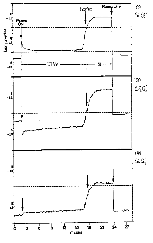
Fig. 4: Partial pressure-time plots for three species suitable for end-point detection during the reactive ion etching (CF2Cl2 plasma) of a TiW/Si interface. (from A.P. Day et al., Semiconductor International 12, 110 (1989).
 Back to Introduction, forward to next lecture, or go to the Bristol Chemistry Home Page