


Dr Paul May, S103A, email: paul.may@bris.ac.uk

In this lecture we shall look a bit more closely at some of the fundamental physics and chemistry occurring within the low pressure plasmas used for semiconductor processing. We shall mainly be concerned with the energies of the various species, such as electrons and ions, within the plasma, and their effect upon etching characteristics. When considering RF plasmas, it is convenient to divide the system into two separate regions, the bulk plasma and the sheath. It is reasonable to do this, since the physics occurring in these 2 regions is very different. We shall also limit our discussion to parallel plate RF plasmas, since these are the most commonly used.
One of the most important concepts in the description of electrical discharges is the idea of a sheath region surrounding any surface in contact with the plasma. This includes the electrodes, the substrate (which normally sits on one of the electrodes), and any probe we may wish to insert into the plasma for diagnostic purposes. It is the difference between the electrical potential between the plasma region and this sheath region that directly leads to positive ion bombardment of the surface, and hence to etching.
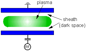
If an electrically isolated substrate is inserted into a plasma, it will initially be struck by positive ions and electrons. The flux of each species, however, will be unequal as a result of the much higher speed of the electrons, and the substrate begins to charge negatively with respect to the plasma. This excess negative charge density around the substrate is called the space-charge, or sheath. The substrate will continue to charge negatively until the electron flux is reduced by repulsion just enough to balance the ion flux. The potential held by an isolated substrate in the plasma is known as the 'floating potential', Vf, since the potential 'floats' to a value sufficient to maintain an equal flux of positive and negative species.
Except around disturbances such as these, the remainder of the plasma is at equipotential. This potential is termed the 'plasma potential', Vp. For DC plasmas, Vp is constant, but for AC or RF plasmas, Vp oscillates with the voltage waveform applied to the powered electrode, V0(t). The potential difference between the floating potential and the plasma potential (Vp-Vf) is the 'sheath potential'. This is the magnitude of the energy barrier which an electron must surmount in order to reach the substrate. It is also the potential through which a positive ion is accelerated onto the substrate.
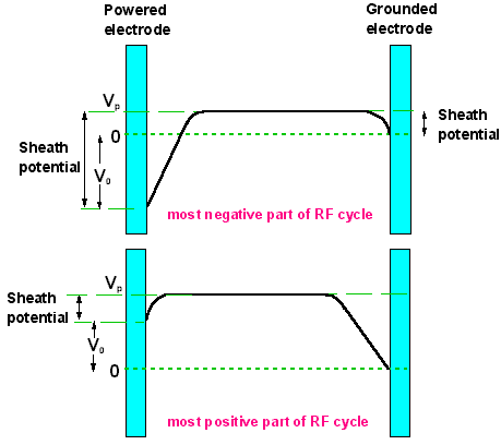 |
Diagram illustrating the relationship between the applied RF voltage, V0, the plasma potential, Vp, and the sheath voltages developed at either electrode. Note these are shown for only 2 instants in time, when V0 is at its most negative (top) and most positive (bottom), and for the case of equal area electrodes (see later). |
Since the sheath is a region over which a negative potential is dropped, electrons are rapidly expelled from the sheath. This loss of electron density results in a reduction of electron impact excitation reactions in that region. Since such reactions lead to fluorescent emission from excited species, the sheath region does not glow as much as the plasma bulk. So the substrate is surrounded by a comparatively dark space, which may be a few µm to a few mm in size depending upon the plasma conditions.
All surfaces in contact with the plasma are surrounded by a dark space sheath, including the electrodes and walls of the chamber. Most of these surfaces are usually grounded (for safety!), and so their corresponding sheath potentials at any instant in time are equivalent to the plasma potential. The powered electrode however, is capacitively coupled to a generator which provides a potential which oscillates sinusoidally on an RF timescale. Therefore the powered electrode sheath potential can be very large (several hundred V) and will oscillate in magnitude with the applied RF. The sheath will also expand and contract with the RF.
 The RF generator supplies a sinusoidal waveform to the powered electrode, and the plasma potential rises and falls in phase with this. Most RF systems have a variable capacitor between the RF generator and the plasma. This is because in order to ensure maximum power transfer into the plasma, the input impedance of the plasma must equal the output impedance of the generator (normally 50 W). By varying the value of this capacitor the effective impedance of the load (plasma + capacitor) can be made equal to 50 W. However the presence of this blocking capacitor introduces the constraint that no net current can flow during one RF cycle. In other words, the total net charge flow per RF cycle to both electrodes must sum to zero.
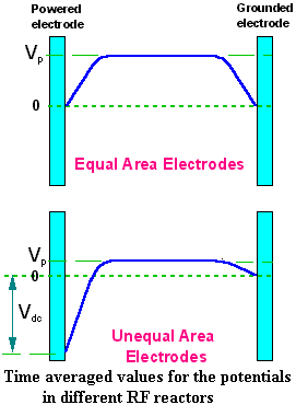
Now, for parallel plate electrodes of equal area, the time averaged potential distribution between the electrodes is shown in the figure to the right, and is symmetrical. But in most RIE systems the surface area of grounded electrode is much larger than that of the powered one. The only way for the plasma to achieve zero charge flow, therefore, is to have very different sheath potentials at the 2 electrodes. Consequently, the powered electrode charges up negatively until enough electrons are repelled for this constraint to be met. This results in a large DC offset being developed between the powered electrode and the plasma. This DC bias (Vdc) can be several hundred volts depending upon the value of the applied RF, V0, and the ratio of the areas of the electrodes. Ions will be accelerated toward the powered electrode through a maximum potential of Vp+Vdc. But since in the case of unequal electrodes, the plasma potential is usually much smaller than the DC bias, a good approximation for the average potential through which an ion is accelerated is simply the DC bias.
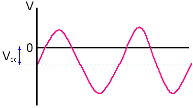 |
Diagram illustrating the variation of the applied RF voltage, V0, with time for an RIE system with unequal sized electrodes. The powered electrode is negative (and therefore experiencing bombardment from positive ions) for most of the RF cycle, and only goes positive for a relatively small time. So not only does the ion bombardment occur for longer, but due to the DC bias, ions impact at higher energies, so increasing etch rates. |
| The time averaged picture of an RIE plasma is shown left. The sheath on the powered electrode is much larger than the one on the grounded electrode. In most RIE systems the substrate to be etched is placed on the powered electrode, since this is where it experiences maximum ion bombardment, and hence where we obtain maximum anisotropy. | 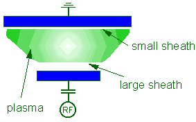 |
Because of the very different conditions existing in the plasma bulk and the sheath regions, we shall consider them separately.
There are 2 main methods of measuring the energies of species within the bulk. The first is optical spectroscopy, which was covered in lecture 2. By using such techniques as Doppler broadening of emission lines and rotational temperature measurements, values for some of the constituents of the plasma can be obtained. However, in order to obtain the energies of electrons or ions within the bulk, we have to turn to electrical measurements using a probe inserted directly into the plasma. Such probes are often termed Langmuir Probes, and may amount to nothing more than a bare wire, which is biased with respect to the plasma, measuring currents as ions and/or electrons are collected.
 |
Left: A Langmuir Probe system commercially produced by a UK company (Hiden Analytical) for the routine analysis of plasma systems. |
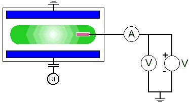 For a single probe introduced into a dry etch reactor, the wall or an electrode must be included in the circuit to pick up the return current from the probe. As the voltage on the probe is biased negatively or positively, the I-V characteristics of the plasma can be measured, and in principle, be related to plasma parameters such as electron temperature and density. Care needs to be taken, though, when interpreting the data from such probes. When a probe is inserted into a plasma it strongly perturbs the potential over a small region by creating a sheath. This means that the data analysis is always somewhat ambiguous, and a full analysis requires knowledge of the interaction between plasma and surface, and the charged carrier flow within the sheath, as well as assumptions about the collection radius of the probe. In RF plasmas especially, RF interference can be tricky to eliminate, and in the reactive plasmas used for etching it is often difficult to prevent the probe from etching away before any useful measurements can be made.
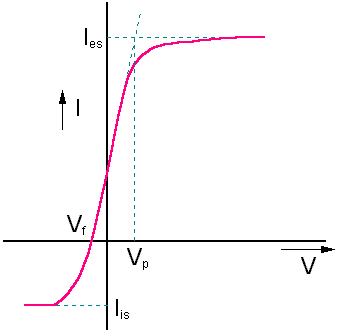 Nevertheless, some very important measurements can be made with probes. The ideal I-V characteristics of such a single probe are shown to the left. If we assume that the current drawn by the probe from the plasma is positive, when the probe bias V is very negative with respect to the plasma potential, Vp, the electric field around the probe will prevent all but the most energetic electrons from reaching the probe, effectively reducing the electron current to zero. The current collected by the probe will then be entirely due to positive ions, since these encounter only an attracting field. This point is called the 'ion-saturation current', Iis.
As the probe bias is increased, the number of electrons which is able to overcome the repulsive electric field and so contribute a negative current increases exponentially. Eventually the electron current collected is equal to -Iis, so that the total current is zero. At this point the floating potential is reached. Further increase of the probe bias to Vp allows the electron current to totally dominate the ion current. At Vp, electrons are unrestricted from being collected by the probe. Any further increase in bias will simply add energy to the electrons, not the current drawn. Hence the term 'electron-saturation current', Ies.
Note that this is the ideal I-V characteristics, ignoring the 'disturbing' processes such as bombardment of the probe by high energy electrons, emission of secondary electrons from the probe, and the probe etching away!
From the floating potential we can calculate the electron temperature, Te, since:

where k is Boltzmann's constant, me is the mass of an electron and mi is the 'average' ion mass (not always an obvious number, particularly in complicated mixed gas plasmas). Also, using the measured value of Iis we can get the electron density and temperature.
One problem with sampling from RF plasmas is that the DC probe only measures instantaneous, average values. Due to the complex chamber geometry, the rapidly varying plasma potential is not actually sinusoidal (see later), so its average may not be zero. This will give an unknown net DC offset to any probe measurement, confusing the values. One way to try to avoid this is to feed a signal directly from the RF input (beyond the capacitance matching network) onto the single probe, in the hope that this signal will cancel out the variation in the plasma potential. In practice, such 'RF compensated' probes have given valuable results, but are still not perfect since the waveform of the signal taken from the matching network is not exactly the same as the plasma potential.
In inductively coupled RF and electrodeless discharges there is often no suitable pick-up electrode for the return current. In this case double or multiple probes are used. These probes are completely floating and the external probe circuit is isolated from ground. Thus the probes should follow changes in the plasma potential (as long as the changes are not too fast), so cancelling the unwanted DC offset in the probe measurements.
From probe measurements and other sources, we now know approximate values for the energies of important species within typical RF parallel plate reactors. The energy distributions of most of the species are close to Maxwellian, and so they can be considered to have a 'temperature'. Recall that the conversion factor is KE=(3/2)kT, where T is in Kelvin, and that if you wish the energy in eV you must divide by the electronic charge. For reference, the energy corresponding to room temperature 300 K is ~ 0.04 eV. The 3 main species types within a plasma (ignoring photons), namely ions, electrons and neutrals, all have different effective temperatures.
| Process Gas | EACS 10-16 cm2 eV | kth 10-8 cm3 s-1 |
|---|---|---|
| CCl4 | 24.9 | 23.7 |
| SF6 | 11.1 | 24.9 |
| CFCl3 | 6.4 | 1.2 |
| Cl2 | ~3.0 | ~20.0 |
| CF2Cl2 | 0.66 | 0.012 |
| CF4 | < 0.1 | < 10-4 |
| N2 | 0.0 | 0.0 |
| Ar | 0.0 | 0.0 |
These are discharges consisting mainly of species which do not form negative ions easily. Examples are all noble gases, such as Ar, He, and some unreactive gases like N2. In these plasmas, the number of +ve ions is almost exactly equal to the number of electrons, although both are still much smaller than the number of neutrals. Because of the relatively large number of electrons, EP plasmas are easily initiated and can be sustained at very low power levels. EP gases such as Ar or N2 are often added to other types of plasmas to stabilise them by increasing the electron density within the plasma.
By contrast, EN plasmas contain a significant number of species which have a positive electron affinity. In these cases the number of free electrons is significantly reduced as a result of capture by EN species to form negative ions. A typical reaction might be:
e + CCl4 ![]() CCl4-
CCl4- ![]() CCl3 + Cl-
CCl3 + Cl-
In CCl4 plasmas the number of electrons can be up to 100 times less than the number of +ve ions, with overall charge neutrality being maintained by large numbers of -ve ions. The relative lack of electrons inhibits efficient energy transfer into the discharge from the applied electric field, and therefore EN plasmas require higher powers to sustain them and are difficult to initiate. This make EN plasmas unstable, and often non-uniform. The electron temperature is also much higher than in EP plasmas since (a) the low energy electrons are removed by attachment reactions, and (b) the energy put into the plasma by the electric field is distributed to fewer electrons, making the average energy per free electron larger.
Some process gases exhibit small (but non-zero) electron attachment cross-sections. Consequently, these plasmas form some negative ions, but the number of electrons is still greater than the number of negative ions, so these plasmas cannot be called true EN plasmas. Examples of these intermediate plasmas are: CH4, H2, O2 and to some extent CF4. As might be expected, intermediate plasmas exhibit features somewhere between the extremes shown by EP and EN plasmas.
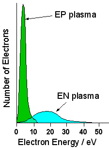 | Electron Energy Distributions obtained by Langmuir Probe measurements for N2 (an EP plasma) and CCl4 (an EN plasma). The N2 distribution is concentrated at low energies, whereas the CCl4 distribution shows a much higher overall energy with a tail extending to ~40 eV. The absolute number of electrons in the CCl4 plasma was measured to be 100 times less than in the N2 plasma. [Data from C.C. Welch, 'Electrical Properties of Glow Discharge Plasmas and their Relation to Dry Etching', MSc thesis, Thames Polytechnic, 1987.] |
We now turn to the energy of species, particularly ions, within the plasma sheath. These are the most important since it is the bombardment of the substrate by these energetic ions that is responsible for the etching process. Positive ions from the plasma bulk at about ambient energy (0.04-0.05 eV), drift around until they encounter the edge of the sheath. At this point they then experience a strong electric field, which begins to accelerate them towards the electrode. In a DC discharge the sheath height is constant, and so all the ions strike the electrode with the maximum sheath voltage.

But in an AC plasma, the sheath is oscillating, and at low frequencies, therefore, the sheath may decrease in width to its minimum value for a significant portion of the time. Therefore the ions will either strike the electrode with the maximum or the minimum sheath potential, depending upon what phase of the AC they initially entered the sheath region. The diagram below shows a low frequency sheath potential that is varying with time as an approximate square wave. Ion (a) encounters the sheath at its maximum, and so experiences the maximum acceleration and strikes the electrode with Emax. In contrast, ion (b) encounters the sheath at its minimum value, and so only experiences the minimum acceleration before striking the electrode with Emin. We thus get a ion energy distribution (IED) with two sharp peaks.

At higher frequencies, the sheath is oscillating up and down so fast that it may make many oscillations during the time it takes for the ion to traverse the thickness of the sheath. When the ion is inside the sheath it will experience acceleration, but when the sheath drops away the ion will continue in free flight until the sheath re-envelops it at the next cycle. Thus the ions will see many successive stages of acceleration interspersed with periods of free flight. As well as those ions which obtain the maximum and minimum energies, many ions will obtain energies somewhere in between. The IED that results is a saddle shape.

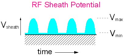
In a real RF system however, things are more complicated. First, the form of the sheath potential is not a square wave. In fact, it is more like a rectified sinusoid, as shown in the diagram below.
Also, in real RF systems we are operating at pressures of a few 10's of mTorr, making the mean free path for ions less than the sheath width. This means the ions will no longer travel ballistically through the sheath, but will experience many collisions with neutral gas molecules before striking the electrode. These collisions cause the ions to lose energy, smearing out the IED.
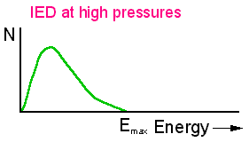
Thus ions strike the electrode with many different energies, all much lower than Emax. Another effect of the collisions within the sheath is that the neutrals which are struck by the fast-moving ions obtain quite a bit of energy by momentum transfer, and themselves get scattered forward, toward the electrode. Thus the electrode is also struck by relatively fast moving neutrals as well.
So the system is very complicated indeed, and it is no easy matter to calculate the exact energy with which particles strike the substrate - or indeed, what the particles actually are. It is no surprise, therefore, that in practice, the value of the DC bias (a number which all modern etchers monitor) is often taken as a rough guide to the energy at which an 'average particle' strikes the substrate.
Measuring the IED with which ions strike the electrodes is not simple. Two basic methods have been developed. The first involves drilling a small hole in the electrode through which the ions are sampled. Behind this hole is a quadrupole mass spectrometer coupled to an ion energy analyser. So long as the hole is small enough that it doesn't perturb the sheath region, and thin enough that ions do not scatter from the sidewalls, some very nice IEDS can be obtained. Another method is to use a retarding field analyser positioned on one of the electrodes. This acts as a high pass filter - the field on the analyser can be ramped up to repel all ions with energy less than the potential on the analyser.
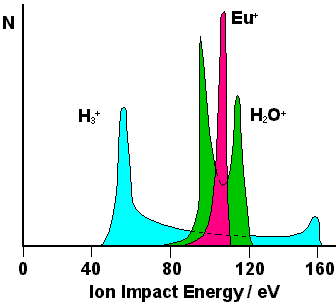 | Ion Energy Distributions measured on the powered electrode of a 13.56 MHz RF etcher at low pressure using a quadrupole mass spectrometer. The saddle shape can be seen, as can the mass discrimination effect of the oscillating RF. The separation between the peaks depends upon many factors, including V0 and the sheath thickness, and goes as mi-½. |
 Back to Introduction or go to the Bristol Chemistry Home Page