
Professor Mike Ashfold, email: mike.ashfold@bris.ac.uk
If we have two energy states E1 and E2 in an atom, the frequency of an emitted or absorbed photon is given by:
E1 - E2 = hn, (1)
where is the frequency and h is the Planck constant, 6.626 x 10⁻³⁴ J s.
Electrons in an atom have angular momentum associated both with orbital motion of the electrons around the atomic nucleus and with intrinsic electron spin. The coupling of these two sources of angular momentum to give the total electronic angular momentum is discussed further below.
In the specific case of atomic hydrogen, the energy associated with a transition between states with energies E1 and E2 is given by
hn = R (2)
(2)
where R is the Rydberg constant and n1 and n2 are integers, termed the principal quantum numbers of states 1 and 2. The principal quantum number can take any value in the range 1,2,3,...... Writing n1 = 1 and n2 = ![]() , we obtain the energy (the so called ionisation potential) required to remove an electron from a hydrogen atom: I.P. (H) = 13.598 eV.
, we obtain the energy (the so called ionisation potential) required to remove an electron from a hydrogen atom: I.P. (H) = 13.598 eV.
Solution of the Schrödinger equation for the hydrogen atom reveals a further quantum number l which designates the net orbital angular momentum of the electrons. s, p and d electrons have l = 0, 1 and 2, respectively. From a more sophisticated relativistic treatment the quantum number s for the electron spin also emerges. s takes the value ½. Electrons in hydrogen atoms may therefore be designated by three quantum numbers n, l and s. Less rigorously we may also designate electrons by these three quantum numbers in many-electron atoms.
A given atom comprises a nucleus and the requisite number of electrons to satisfy overall charge neutrality. The way in which these electrons are distributed amongst the various atomic orbitals is called the atomic configuration; different electronic configurations have different energies.
Consider the case of a carbon atom. Its ground state configuration is 1s22s22p2, implying 2 electrons in the 1s orbital, 2 in the 2s orbital etc. The lowest energy state arising from its first excited configuration - 1s22s22p13s1 lies ~7.95 eV higher in energy. In the case of atomic fluorine, the ground state (configuration 1s22s22p5) and the first excited configuration - 1s22s22p43s1 - are separated by 13.00 eV. However the description of the energy levels of atoms possesses a further layer of complication which it is vital to probe for an understanding of atomic spectroscopy. The configuration of electrons described by (say) ls22s22p43s1 in atomic F can assume different energies according to the different ways in which the orbital and spin angular momenta of the electrons couple together. Orbital motions of electrons are effectively orbital motions of charges; these motions therefore generate magnetic fields. Equally the 'spinning' motion of the electron, viewed classically, generates a magnetic field. The motions of the electrons, both orbital and spin, therefore interact ('couple') with one another.
Consider an atom with one unpaired electron. In the course of its motion within the atom, electron spin and orbital angular momenta are continually being exchanged and neither is constant with time. Therefore neither quantity can be evaluated in terms of a 'good' quantum number, for a 'good' quantum number is by definition one that describes a quantity that does not change as motion proceeds. Angular momenta are vector quantities and it turns out that vector sums of the orbital and spin angular momenta are time independent since these vector sums represent the total angular momentum of the electron - and this is a 'constant of the motion'. Thus we introduce a new quantum number, j, which is the vector sum of l and s. For an unpaired p-electron l = 1 and s = ½ hence j = ½ or 1½. j is a 'good' quantum number. For a single unpaired s electron j = ½ only, since l = 0 for an s-electron.
Two further points should be noted here:
(i) the behaviour with regard to angular momentum coupling of an atom with one p-electron is the same as for an atom containing 5 p-electrons (but see Landé's rule, section iii). Thus the states of boron, with configuration ls22s22p1, are the same as those of fluorine ...2p5. This behaviour can be generalised and we find that states of atoms with two p-electrons are the same as those with four p-electrons etc.
(ii) the states associated with a particular configuration of electrons are determined by the electrons in incompletely filled orbitals. Thus when considering the states of (say) a ground state Cl atom we need only consider the five 3p electrons, and do not need to include any contributions from electrons in filled inner orbitals (3s, 2p etc.). An obvious result of this is that the states of atomic Cl are the same as those of fluorine.
Consider now an atom with two (or four) p electrons. The orbital motions and spins will couple but there are now two ways in which one can imagine this coupling as taking place. In the first, called L,S or Russell-Saunders coupling, orbital motions of different electrons are strongly coupled and sum vectorially to give a total orbital electronic angular momentum represented by the quantum number L. Similarly, the spins of different electrons couple to give an overall spin angular momentum represented by the quantum number S. Again neither L nor S is a 'good' quantum number, but their vector sum representing the total angular momentum is a constant of the motion and this total may be represented by the 'good' quantum number, J. Thus to find J states of the electron configuration we vector couple individual l's to give L and s's to give S and then vector couple L and S to give the various possible resultants J, hence the name 'L,S' coupling. The second way in which one can imagine that orbital and spin motions might couple is a mechanism in which the orbital and spin motions for each separate electron couple quite strongly. In this case we assign a j for each electron, and then couple these j's together vectorially. This type of coupling is called 'j,j' coupling. Physically L,S coupling takes place in atoms in which spin-orbit coupling is significantly weaker than spin-spin or orbit-orbit coupling, whilst j,j coupling dominates in cases where spin-orbit coupling is strong. Experimentally (see below) it is found that in lighter atoms, i.e. the first and at least part of the second row of the periodic table L,S coupling is a good description. For heavier elements e.g. Cl, j,j effects become increasingly important. In heavy atoms electrons move faster, generate larger magnetic fields, and stronger spin-orbit interaction. Of course both L,S and j,j coupling represent limits and in any atom neither is likely to provide a perfect description. Since we deal largely with lighter atoms in which L,S coupling dominates we will follow this scheme and its appropriate notation throughout this lecture.
Returning to our example of an atom with 2 or 4 p electrons, the l's can couple vectorially to yield L = 0, 1 or 2 represented in the term symbol for the electronic state by S, P and D, respectively. The s's can couple to yield S = 0 and 1. These are often represented by2S+1LJ
For ground state C atoms with two p electrons, there thus exist state with term symbol is 3P0, 3P1 and 3P2. Reasons for writing 2S+1 on the top left will become clear below.
| Electrons | S | L | Orbital term symbol |
|---|---|---|---|
| s1 + p1 | 0,1 | 1 | P |
| p1 + p1 | 0,1 | 0,1,2 | S,P,D |
| p1 + d1 | 0,1 | 1,2,3 | P,D,F |
| d1 + d1 | 0,1 | 0,1,2,3,4 | S,P,D,F,G |
Table 1 shows the L and S values and the resulting orbital term symbols that result from coupling of two 2 electrons of various types. Similar and more complicated results could be written down for 3 electrons.
From the values of L and S in Table 1 we can derive values of J since
J = L+S, L+S-1, L+S-2........... L-S; J>= 0.
We see therefore that there are 2S+1 values of J for a given L. However, in constructing atomic states we must observe the Pauli Exclusion principle, which states that no two electrons may have the same set of quantum numbers. Consider again the case of a ground state carbon atom with configuration .....2p2. Both electrons with the same n and l quantum numbers. If we also allow them the same spin orientation (i.e. both ![]() or both
or both ![]() - two possible representations of S = 1) we would violate the Pauli principle. As a result, the 3D state of C that could, in principle, result from coupling these two 2p electrons does not exist. Note, however, that 3D
states are formed from excited configurations like ....2p13p1 since now the two electrons have different principle quantum numbers.
- two possible representations of S = 1) we would violate the Pauli principle. As a result, the 3D state of C that could, in principle, result from coupling these two 2p electrons does not exist. Note, however, that 3D
states are formed from excited configurations like ....2p13p1 since now the two electrons have different principle quantum numbers.
Each electronic state represented by the appropriate term symbol in fact represents several degenerate sub-levels (i.e. levels of the same energy). The degeneracy of these sub-levels is lifted in the presence of a magnetic field, thus they are often referred to as 'magnetic sub-levels'. There are 2S+1 sub-levels associated with a state of total spin S. Such a state is said to be 2S+1 degenerate, and its 'multiplicity' is equal to 2S+1. Thus a single electron results in a doubly degenerate state (i.e. spin 'up', ![]() , or 'down',
, or 'down', ![]() ), often referred to as a 'doublet state', two electrons can form singlet or triplet states, three can form doublet or quartet states, etc. Hence the term symbol representation 2S+1.
), often referred to as a 'doublet state', two electrons can form singlet or triplet states, three can form doublet or quartet states, etc. Hence the term symbol representation 2S+1.
Empirical rules, known as Hund's Rules, give the energy ordering of different electronic states arising from the same electron configuration.
Rule 1: The state of maximum multiplicity lies lowest in energy.
Rule 2: In the case that a given configuration supports more than one state of a given multiplicity, the state with the highest L quantum number lies lowest in energy. e.g. if a given configuration could support the following states
1S, 3S, 3F, 1D
then their energetic ordering would be as follows:
3F < 3S < 1D < 1S
.Rule 3: gives the ordering of the J states associated with a given term. If the shell is less than half-filled (e.g. p1, p2, p3), then the level with the lowest J value lies lowest in energy. In the case of more than half-filled shells (e.g. p4, p5, d6), the level with the highest J value lies lowest in energy. There is also a quantitative result which states that the separation of members of a multiplet between members with total angular momentum quantum numbers J and J+1 is proportional to J+1 ('the Landé interval rule').
Parity is a quantum mechanical concept with no classical analogue which is essentially a reflection of the mathematical properties of the wave function for the atomic state. The wave function f(x,y,z) is of even parity if f(x,y,z) = f(-x,-y,-z) and of odd parity if f(x,y,z) = -f (-x,-y,-z). The parity of the wave function is given by ![]() . The importance of parity is highlighted in Section (vi), below. Odd parity is donated by a superscripted 'o' on the right hand side of the term symbol.
. The importance of parity is highlighted in Section (vi), below. Odd parity is donated by a superscripted 'o' on the right hand side of the term symbol.
TABLE 2: Electronic configurations and term symbols for various of the electronic states of C, N, O, F, F+ and Cl. Term values (in cm-1) are shown in the last column.
| Element | Configuration | Term Symbol | Term Value/cm-1 |
|---|---|---|---|
| C | 2s22p2 | 3P0 | 0.0 |
| 3P1 | 16.4 | ||
| 3P2 | 43.5 | ||
| 2s22p2 | 1D2 | 10193.7 | |
| 2s22p2 | 1S0 | 21648.4 | |
| 2s12p3 | 5S2o | 33735.2 | |
| 2s22p13s1 | 3P0o | 60333.8 | |
| (Rydberg) | 3P1o | 60353.0 | |
| 3P2o | 60393.5 | ||
| N | 2s22p3 | 4S3/2o | 0.0 |
| 2s22p3 | 2D5/2o | 19223 | |
| 2D3/2o | 19231 | ||
| 2s22p3 | 2P1/2o,2P3/2o | 28840 | |
| 2s22p23s1 | 4P1/2 | 83285.5 | |
| (Rydberg) | 4P3/2 | 83319.3 | |
| 4P5/2 | 83366.0 | ||
| O | 2s22p4 | 3P2 | 0.0 |
| 3P1 | 158.5 | ||
| 3P0 | 226.5 | ||
| 2s22p4 | 1D2 | 15867.7 | |
| 2s22p4 | 1S0 | 33792.4 | |
| 2s22p33s1 | 5S2o | 73767.8 | |
| 2s22p33s1 | 3S1o | 76794.7 | |
| F | 2s22p5 | 2P3/2o | 0.0 |
| 2P1/2o | 404.0 | ||
| 2s22p43s1 | 4P5/2 | 102406.5 | |
| (Rydberg) | 4P3/2 | 102681.2 | |
| 4P1/2 | 102841.2 | ||
| 2s22p43s1 | 2P3/2 | 104731.9 | |
| (Rydberg) | 2P1/2 | 105057.1 | |
| 2s22p43p1 | 4P5/2o | 115918.7 | |
| (Rydberg) | 4P3/2o | 116041.7 | |
| 4P1/2o | 116144.4 | ||
| F+ | 2s22p4 | 3P2 | 0.0 |
| 3P1 | 341.8 | ||
| 3P0 | 490.6 | ||
| 2s22p4 | 1D2 | 20873 | |
| 2s22p4 | 1S0 | 44919 | |
| 2s12p5 | 3P2o | 164797.7 | |
| 3P1o | 165107.1 | ||
| 3P0o | 165281.0 | ||
| 2s22p33s1 | 5S2o | 176654.2 | |
| 2s22p33s1 | 3S1o | 182865.2 | |
| 2s22p33p1 | 5P1 | 202609.7 | |
| 5P2 | 202621.0 | ||
| 5P3 | 202640.5 | ||
| Cl | 3s23p5 | 2P3/2o | 0.0 |
| 2P1/2o | 881 | ||
| 3s23p44s1 | 4P5/2 | 71954.0 | |
| (Rydberg) | 4P3/2 | 72484.2 | |
| 4P1/2 | 72822.6 | ||
| 3s23p44p1 | 2D5/2o | 84643.7 | |
| (Rydberg) | 2D3/2o | 84984.0 |
Table 2 lists various of the electron configurations and some of corresponding states (and term symbols) for atomic C, N, O, F, F+ and Cl. Some of the excited states involve an electron with principle quantum number greater than that of any electron contributing to the ground state configuration. Such states are called Rydberg states.
We have now covered sufficient background to move on to consider transitions between atomic states. It is worth mentioning one omission: we have not included nuclear spin in our discussion. Normally splittings due to nuclear spin are so small that they lie well within the Doppler width of atomic emission lines. Thus they are not generally resolvable using standard spectroscopic techniques. Nuclear spin splittings may, however, make a significant contribution to the apparent widths of spectral lines (e.g. in certain transitions of the F atom under high resolution).
Transitions between states such as those shown in Table 2 are governed by selection rules. These may be summarised as follows:
Comments on selection rules:
a) The parity rule arises because the dipole operator in the transition moment integral, whose square is proportional to the transition probability, is itself of odd parity. The dipole operator may therefore only couple wavefunctions of opposite parity.
b) The spin rule reflects the physical requirement that the only means by which a spin can be 'flipped' in a transition is through the action of a magnetic field on the electron spin magnetic moment. Magnetic interaction with the magnetic component of electromagnetic radiation is about 105 times weaker than electric field interactions with the induced dipole in the emitting (or absorbing) atom.
c) The DL and DJ selection rules both reflect the property of the photon that it has one unit of angular momentum. In the interaction with the atom total angular momentum must be conserved according to the rules of vector addition.
d) These rules assume that the interactions within the atom are in the weak spin-orbit coupling regime (i.e. L,S coupling). Thus L and S, whilst in fact coupled to give J, are not far from being 'good' quantum numbers and it is meaningful to specify states according to their spins as singlet, doublet, triplet, etc. In cases where j,j coupling becomes important the spin rule breaks down and as j,j coupling increases in strength the rule must be completely abandoned. In atomic Cl, the transition 4P - 2D is allowed for example, although it is 10 times weaker than typical 'spin allowed' transitions. In a heavy atom like Hg, however, transitions which involve a change in S are just as strong as those which do not.
To illustrate the operation of selection rules we consider the example of F+, shown in fig. 1.
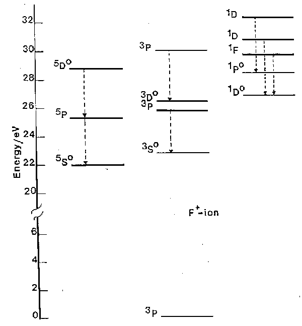
Fig. 1. A subset of the energy levels of the F+ ion, highlighting various of the spin-allowed transitions (dashed arrows). Note the 5So, 1Do and 1Po highly excited, but metastable, states. (1 eV = 8065.5 cm-1).
a) The DS = 0 spin selection rule ensures that the transitions divide essentially into three groups, those involving singlet states, those involving triplet states and those involving quintets.
b) Only a fraction of the allowed transitions are generally observed for experimental reasons. Working at atmospheric pressure one is unable to observe radiation at wavelengths <200 nm since molecular oxygen begins to absorb strongly from thereon. Thus we can observe no transitions directly to the ground 3P state, e.g. the 3S - 3P transition which occurs a 54.7 nm.
c) The spin selection rule can lead atoms to become 'stranded' with high internal energy, in so-called metastable states. The 1D, 1S and 5SO states of F+ (at 20873 cm-1, 44919 cm-1 and 176654 cm-1 above the ground state, respectively) are examples of such metastable states. Population in metastable states in discharges used in etching is of fundamental importance to etch mechanisms. Atomic chlorine, being heavier, exhibits stronger spin-orbit coupling. The S = 0 spin selection rule is thus less rigorous, its quartet-doublet transitions are correspondingly more probable, and Cl (and Cl+) have no really metastable states.
d) In fig. 1 it is clear that emission is observed from quite highly excited states of ions. For example the 5D state of F+ is more than 28.5 eV (2750 kJ mol-1) above the ground state of the ion. Similarly large excitations are seen in many other atomic and ionic species. Atomic, ionic and also molecular species (ionic and neutral) generally achieve these high energy states through inelastic collisions with energetic electrons in the discharge. Some atomic and molecular emission can originate from chemiluminescent processes in which the excited electronic states of certain species (e.g. SiCl) are formed directly in the chemical reactions creating those species.
The lifetimes, t, of atomic transitions are typically of the order of tens of nanoseconds though the range of values is wide as it must be from the inverse (frequency)3 relationship
t =  (3)
(3)
where g1 is the multiplicity of the lower level in the transition and µ is the dipole moment associated with the transition. The weakly allowed Cl 4P - 2D transition linking the last two groups of states shown in Table 2 has t~2 µs. This may be compared with a spin conserving transition of about the same frequency, 4P - 4S, for which t = 40 ns.
An important facet of these values of lifetime is that no significant quenching takes place of the excited states of atoms and atomic ions in the discharge. It is also worth noting that short lifetimes imply high Einstein A-coefficients and thus high emission intensities.
Many concepts of atomic spectroscopy can be carried over into molecular spectroscopy, e.g. eq.1, many aspects of term symbols, the existence of metastables, etc. The characteristic appearance of molecular emission spectra is however very different from that of atoms or atomic ions. Atomic spectra generally consist of many sharp lines which, in the absence of spectral overlap, appear symmetrical. Molecular spectra may be of widely differing appearance but often exhibit several groups of very closely spaced lines, each group called a 'band' or 'sub-band', separated by roughly equal frequency intervals. Moreover, the appearance of such spectra is very different if spectra are run at low or high resolution, or at high or low gas temperatures. At low resolution, 'bands' will appear as broad humps with little identifiable structure whereas at high resolution bands may be resolved into identifiable sharp lines. Good examples of molecular (and atomic) emission spectra are shown in fig.2, which shows spectra of the emission from an RF discharge in a CF4/O2 mixture, with (lower trace) and without (upper trace) a silicon substrate, over a limited range of UV wavelengths. The shorter wavelength traces (left) show characteristic pairs of partially resolved sub-bands (see below in (iv)) associated with electronically excited CF radicals (labelled A), whilst the longer wavelength traces (right) show three sub-bands (B) due to CO and a pair of peaks (C) attributable to electronically excited CO2+. The sharp features labelled F and D, the intensities of which are much enhanced when the substrate is present, are attributable to Si atoms and F+ ions, respectively. Features such as these could be useful in etch end-point determination. It is spectra of the type shown in fig.2 that we need to be able to interpret and analyse in order to make use of the power of atomic and molecular spectroscopy as a diagnostic tool in etching processes.
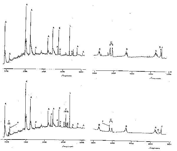
Fig.2. Part of the emission spectrum observed using an RF discharge in a CF4/8% O2 mixture with (lower trace) and without (upper trace) an Si wafer. Process conditions: 62.5 kHz, 0.3
W cm-2, 180 mTorr, flow rate 1.7 sccm.
Key to assignments: A: CO+, B: CO, C: CO2+,
D: F+, E: C atom, F: Si atom, H: CF2 radical, J: N2 (from imperfect vacuum), and L: Hg (calibration line).
Unlike atoms, molecules can vibrate and rotate and have quantised vibrational and rotational energy levels. When a molecule undergoes transition from one electronic state to another it may simultaneously change its vibrational and rotational quantum numbers. The occurrence of several bands attributable to the same species (e.g. in fig.2) reflects the fact that the emitting molecules may end up in several different vibrational levels of the lower electronic state. The detailed structure of each band reflects the nature of the electronic states involved in the transition, and the allowed changes in rotational quantum number. In order to understand what we see we must therefore look more closely into molecular vibrations and rotations associated with electronic transitions, so-called 'rovibronic transitions'. Fortunately it turns out to be unnecessary to deal with rotation in any detail for our present purposes. Suffice it to say that the presence of rotation produces highly structured broadening of electronic emission bands since these are made up of a large number of not quite energetically superposed rovibronic lines. These lines are classified into the well-known P, Q and R branches of IR spectroscopy. Two features may be mentioned (i) the Q-branches often consist of lines which are very close in energy and, as in IR spectra, may show up as quite sharp unresolved spikes in the envelope of a rovibronic band; for reasons not discussed here P and R branches often merge when one of the two 'turns back' so forming a characteristic 'band head'. This is clearly seen in the case of the CO+ emission bands in fig.2. Note that these bands shade towards the red end of the spectrum and are therefore termed 'red degraded'. Such information allows one to deduce that the internuclear distance in the upper state is (in this case) longer than in the lower electronic state. Whether the band appears red or blue degraded can be a useful diagnostic of the identity of the emitting species.
To a first approximation the energy of a molecule can be split up into separate electronic, vibrational and rotational parts
Etotal = Ee + Ev + ER (4)
Crudely one may therefore split up a discussion of molecular energy levels into electronic, vibrational and rotational. As suggested above, the combined presence of these three contributions then gives rise to the spectra which one observes experimentally.
All the emissions which we encounter will be between different electronic states rather than between vibrational or rotational states (of the same electronic states). We limit ourselves exclusively to a consideration of diatomic species. The only emitting triatomics which one is likely to encounter in this subject appear to be CF2 and CO2+ (and maybe CC12) and for the sake of one or two molecules it is not worth a lengthy excursion into spectroscopic theory.
In an atom we specify electrons by n and l. In a diatomic molecule we specify electrons by n and l and make the connection with atoms by considering the equivalent atom - that is the atom with the same number of electrons as the diatomic. This equivalent atom is usually referred to as the "united atom" corresponding to the diatomic. Examples are He+ for H2+ or the F atom for OH. In a diatomic there is an electric field due to the nuclei along the internuclear axis. The angular momentum vector of any electron may be oriented with respect to the internuclear axis (i.e. the field direction) only in those directions such that the component of angular momentum along the inter-nuclear axis is given by ml = l, l-1, l-2,...,-l units of h/2p. l is defined as the absolute value of ml, the absolute value being used since states of the electrons differ in energy only through the magnitude of ml and not through its sign. Electrons with l = 0 are called s electrons, those with l = 1 , p electrons, l = 2, d electrons, etc by analogy with s, p, d, .... electrons. s, p, d, ... atomic orbitals now become s, p, d molecular orbitals. In order to distinguish different electrons we use the corresponding orbitals of the united atom and therefore write 1ss, 2ss, 2pp, 3ss, 3pp, 3dd, etc.
A further property of molecular orbitals, applying only to molecules with a centre of symmetry (e.g. homonuclear diatomics) is their parity. This is established by considering the sign of the wavefunction for the molecular orbital at a particular point and inverting through the centre of symmetry of the molecule until reaching the corresponding position on the other side. If the amplitude of the wavefunction undergoes a change of sign the orbital has a subscript 'u' (for ungerade) appended to it. If there is no change of sign a subscript 'g' (for gerade) is added. Thus one sees orbitals labelled su, pg, etc.
For a given electronic configuration, as for atoms, the total orbital angular momentum of a diatomic molecule is made up from contributions from all electrons. However in a diatomic all components of orbital angular momentum, as specified by naming the electrons s, p, d, .., lie in the direction of the internuclear axis. The total orbital angular momentum L is therefore given by the algebraic sum of the individual orbital angular momenta
L = ![]() (5)
(5)
Thus we obtain L = 0, 1, 2, etc, which are referred to as S, P, D, .... by analogy with S, P, D, ... labels used in atoms. The electron spin angular momenta however add vectorially, as in atoms, to give a resultant S. Thus the molecular analogues of atomic term symbols take the general form
2S+1L(u/g),
where the right subscript applies only in the case of centrosymmetric species.
Consider two electrons in a homonuclear diatomic, one having sg symmetry (i.e. l = 0), the other pu (l = 1). The total orbital angular momentum projection quantum number L = 1, so the system is a P state. Given that there are only two electrons, S = 0 or 1 resulting in singlet or triplet spin multiplicities. Possible states arising therefore from a sg1pu1 configuration are therefore 3Pu and 1Pu. Note that since one electron is in an orbital with g parity (i.e. symmetric with respect to inversion) and the other in a u orbital the resulting product wave function must have u parity.
Now consider a heteronuclear diatomic with electronic configuration p1p1. Given that the li are signed quantities it should be clear that L = 0 or 2; i.e. that this configuration can support S and D states. If we consider how these values of L can arise we can form the D ( L = 2) state, by combining li = -1 and -1 or +1 and +1. These two ways of combining li are degenerate. However the S state can be made by the two angular momenta opposing one another in two ways which turn out to be non-degenerate. These two states can be represented by functions that are respectively symmetric and anti-symmetric with respect to reflection at any plane through the internuclear axis. The respective terms symbols are written S+ and S-. Thus we obtain the following term symbols for the states formed from the configuration p1p1:
1S+, 1S-, 1D, 3S+, 3D
As for atoms, the Pauli Principle must be satisfied. This introduces a restriction in the case that the two p electrons are in the same degenerate pair of p orbitals (but not otherwise), with the result that only the 1S+, 1D and 3S- terms are allowed.
The electronic states of a diatomic are dictated, as for atoms, by the electrons in incompletely filled orbitals. Most electrons will be in the inner, most tightly bound, orbitals with their spins paired and contribute neither to the net orbital nor the net spin angular momentum of the molecule. With a little experience, the electronic state of a diatomic molecule can be predicted readily if the energetic ordering of its orbitals are known, simply by distributing its electrons two per s orbital and four per p or d orbital, starting from the lowest energy and working upwards, and then considering the occupancy of just the highest occupied, incompletely filled, orbitals. The problem is to know the energy ordering. In fact, the ordering of the orbitals (and the energy levels) cannot be known with certainty except through very complicated numerical solutions of the Schrödinger equation for the specific diatomic molecule. The ordering is different for different species, e.g. for H2 the 3ss orbital lies above the 3ps orbital, whereas in N2 the reverse is true.
We should also note that it is possible to make a distinction between those orbitals which, when occupied, make the bond between the constituent atoms stronger and those which make it weaker relative to the free unbonded atoms. Those electrons that make the bond stronger are in so-called bonding orbitals and are termed bonding electrons, while those that make it weaker are in anti-bonding orbitals and are called anti-bonding electrons. Orbitals which are anti-bonding are generally labelled with a * superscript. A third sub-set of orbitals, when occupied, have little effect on the bonding. Such electrons are referred to as non-bonding electrons.
Notwithstanding the uncertainties noted above, molecular orbitals generally fall in the following energetic ordering:
1ss, 1ss*, 2ss, 2ss*, 2ps, 2pp, 2pp*, 2ps*, 3ss, ...........
although the ordering of the 2ps, 2pp, 2pp*, 2ps* group is very sensitive to the nature of the diatomic. For example the above ordering is correct for O2 but incorrect for CO (see below).
If we arrange the 16 electrons in O2 in the above molecular orbitals starting at the lowest energy 1ss orbital we find that the final two electrons need to be placed in the 2pp* orbital, i.e. a p2 (or more strictly, since O2 is homonuclear a pu2) configuration. Recalling our second example in (iii) above we note that three states will derive from this configuration, with term symbols: 1Sg+, 1Dg and 3Sg-. Now consider CO and the CO+ ion, both of which contributed to the emission spectrum shown in fig.2. It turns out that the energetic ordering of the 2ps and 2pp molecular orbitals in both of these species is reversed compared with that listed above. Either way, however, since CO is a 14 electron heteronuclear species the highest occupied molecular orbital in its ground state configuration is fully occupied, there is no net spin or orbital angular momentum, and its ground state term symbol is 1S. CO+ has one less electron and, in its ground state configuration, one unpaired 2ps* electron. Its term symbol will be 2S.
The O2 example above illustrates that more than one electronic state can derive from a single electronic configuration. What is the energetic ordering of these states, i.e. which state is the true ground state and which are excited states? The answer to this question involves use of propensity rules entirely analogous to Hund's rules for atoms. Thus in O2 the ground state is 3Sg-, the first excited state is 1Dg and the second excited state 1Sg+. The 'rules' are essentially as for atoms, i.e. when more than one term arises from a given electronic configuration:
Rule 1: the state of highest multiplicity lies lowest in energy, followed by
Rule 2: in cases where there is more than one term with the same multiplicity the state of highest L lies lowest in energy.
Notation: by convention the ground state term symbol is prefixed with an 'X', the first excited state, of the same spin multiplicity, with an 'A', the second with a 'B', etc. The first excited state of a different multiplicity is prefixed with an 'a', the next with a 'b' etc. Thus the states of O2 considered above are written X3Sg-, a1Dg and b1Sg+.
One may also address the question: what states arise when we allow the electrons to assume excited configurations? A little care is needed here since the spectroscopic characteristics of molecules have themselves been used to determine the ordering of molecular orbitals. It is perhaps more realistic to state that we can understand the formation of the excited states whose nature we have deduced from observational spectroscopic data. With this in mind we take two examples:
(i) CO: the lowest energy excitation involves promotion of one electron from the highest occupied 2ps orbital to the lowest unoccupied 2pp* orbital. The resulting s1p1 excited configuration gives rise to two excited states, with term symbols 3P and 1P, of which (by the molecular analogue of Hund's rules) the former is lower in energy. Slightly higher in energy will be found the 3S and 1S states that result from excitation of a 2ps electron to the antibonding 2ps* orbital. These will be found referenced in spectroscopic textbooks as the a3P and A1P, and b3S and B1S states of CO, respectively. The bands marked B in fig.2 are associated with the b3S - a3P transition.
(ii) CO+: as we have seen, this ion has a 2pp42ps1 configuration in its electronic ground state, with term symbol X2S. The lowest energy excitation involves promotion of one 2pp electron to the singly occupied 2ps orbital, resulting in a A2P excited state. The A2P - X2S transition is responsible for the bands marked A in fig.2.
Just as in atoms, the magnetic fields generated by the moving charges in molecules cause the spin and the orbital angular momenta to couple together. Molecules show an additional complication: the nuclei are seen by the outer electrons as partially shielded charges and therefore the rotation of the nuclear framework itself generates a magnetic field allowing the molecular rotation to couple to the electron spin and/or to the orbital electronic motion. The nature of a molecular spectrum depends critically on the relative strengths of the couplings between these three angular momenta. The two most common cases are:
In Hund's case (a), the coupling of the orbital and spin angular momenta means that L and S (or, strictly, L and S, where S is the axial projection of S) are not well defined quantum numbers but that their vectorial combination, written W, is a good quantum number. The simplest case for which case (a) coupling is applicable is for a 2P state, such as the first excited (A) state of CO+ discussed above. Here W can assume the values L+S or L-S, i.e. 3/2 or 1/2. These resulting 'spin-orbit' states are notated 2P3/2 and 2P1/2 states. As another example, 3D states can have W = 1, 2 or 3. From the viewpoint of spectral interpretation, the key point is that these spin-orbit molecular states, characterised by different quantum numbers, possess different electronic energies. The energy difference between the 2P3/2 and 2P1/2 spin-orbit states is well approximated by the 'spin-orbit coupling constant', A. The value of A varies markedly from molecule to molecule - ranging from 10's to 1000's of cm-1. Such energy splittings can be a very characteristic feature in emission spectra and explains, for example, why the CO+ features in fig.2 (bands A) all appear as doublets.
The energy ordering of Hund's case (a) spin-orbit components follows expectations based on the Landé rule for atoms, i.e. for less than half-filled shells the level with the lowest value of lies lowest in energy whilst for more than half-filled shells the converse is true. The A2P state of CO+ derives from a 2pp3 (i.e. more than half-filled) configuration and thus its 2P3/2 component lies lower in energy than the 2P1/2 state. Each spin-orbit component of a Hund's case (a) molecule has its own associated stack of rotational and vibrational energy levels. The rotational levels are labelled by J, the quantum number for the total angular momentum of the molecule,i.e. the orbit, spin and framework rotation all coupled together. Clearly J cannot be less than W, and the lowest rotational level is ascribed a quantum number J = W.
Hund's case (b) molecules do not exhibit the large energy level splittings seen in case (a) situations. Instead the framework rotation couples vectorially with the total spin, S, resulting in small (a few cm-1) splittings of each rotational level. Thus, in contrast to case (a), levels with the same value of framework rotation quantum number (labelled N) lie close together, and the small spin-rotation energy splittings are generally hard to resolve. The ground X2S state of CO+ provides an example of a Hund's case (b) system.
Again we restrict the discussion to diatomic molecules. The notation adopted to specify vibronic transitions (i.e. transitions involving changes in both the electronic and vibrational state of the molecule) is to append (v', v") after the electronic transition descriptor, where v' is the vibrational quantum number of the upper (emitting) state and v" is the vibrational quantum number of the lower state. For example, the three bands labelled B in fig.2 are, in order of increasing wavelength, the CO(b3S-a3P) (0,0), (0,1) and (0,2) bands.
Such vibronic progressions are often a characteristic feature of a molecular species and the observation of several such appropriately separated features (especially those that are known or predicted to be strong) is a good way to confirming the identification of a spectral carrier. This introduces the question of vibronic transition intensities. The CO(b3S-a3P) (0,0) and (0,1) bands are the most intense, and the (0,v") progression fades with increasing v". The (0,5) band, which occurs at 360.0 nm (not shown in fig.2), is barely discernible. In other diatomic cases, the (0,0) band may be weak or even invisible, whilst transitions involving large changes in the v quantum number may be quite intense.
The relative intensities of vibronic bands are governed by Franck-Condon factors, Sv',v".
Sv',v" = 
i.e. the square of the overlap integral of the vibrational wavefunctions of the ground and excited electronic states. If the bond length of the diatomic changes very little as a result of the electronic excitation associated with the transition then the strongest vibronic bands will tend to be those which involve little or no change in vibrational quantum number, i.e. the (0,0), (1, 1), (2, 2) bands etc. Conversely, if the electronic transition induces a considerable change in equilibrium bond length, such as might be expected, for example, if a bonding electron is promoted to an anti-bonding orbital, then the strongest vibronic transitions will tend to involve large changes in v. Clearly, confidence in a spectral assignment of a spectral carrier can be boosted by the observation not just of a plausible progression, but of a progression exhibiting a sensible intensity distribution. A word of warning is in order here, however. Different sources, e.g. RF, DC or microwave discharges, flames, spark sources etc., may have very different effective vibrational temperatures and thus reported relative intensities derived from observations involving one type of source may not transfer directly to another situation.
As for atoms the total (including rotational) angular momentum quantum number J must change by 0 or 1 and J = 0 ![]() J = 0
is forbidden. Additionally we note that S-S transitions do not support Q-branches (i.e. DJ = 0 transitions).
The electronic quantum numbers and S follow the rules
J = 0
is forbidden. Additionally we note that S-S transitions do not support Q-branches (i.e. DJ = 0 transitions).
The electronic quantum numbers and S follow the rules
DL = 0, ±1; DS = 0,
the latter rule implying that the multiplicity of the state should not change in a transition. Additionally we have the parity selection rules:
S+![]() S+ and S-
S+ and S-![]() S- (S+
S- (S+![]() S- is forbidden),
S- is forbidden),
and
u ![]() g ( u
g ( u ![]() u and
g
u and
g ![]() g are forbidden).
g are forbidden).
Just as in atoms, one important consequence of the conservation of S (or S) in electronic transitions is the existence of metastable excited states of molecules. The a3P state of CO, found in CF4/ 8% O2 RF discharges, is a good example of such a state. CO in its X1S ground state is a very unreactive species: the metastable a3P state however has 6.036 eV of electronic energy and is sufficiently energetic to remove silicon atoms from the surface of a silicon wafer (forming SiC).
Finally we may note that the lifetimes of excited electronic states of diatomic molecules may typically be 10x longer than for atoms but that again little quenching is likely to take place in these time periods, now in the 100 ns to s regime.
From the forgoing it should be clear that the measurement of emitted light from a plasma is relatively facile, but that the interpretation of the resulting spectra often requires much previous knowledge. Other limitations are the fact that only electronically excited species (generally a small fraction of the entire plasma) contribute to the emission - so optical emission spectroscopy (OES) gives little direct information about the relative concentrations of the (more abundant) ground state species. Actinometry has been proposed as a route to alleviating this limitation. It involves adding a small quantity of a noble gas (the actinometer, e.g. Ar) to the reactive plasma. The actinometer is chosen so as to have a threshold energy and cross-section for electron impact excitation similar to that of the species of unknown concentration. The ratio of the emission intensities of the unknown species and the actinometer are then assumed to be equal to the absolute concentration ratios. Since the amount of actinometer is known, the number density of the unknown species can be calculated. Fig.3 shows representative results for atomic F, measured as a function of pressure in a CF4 plasma.
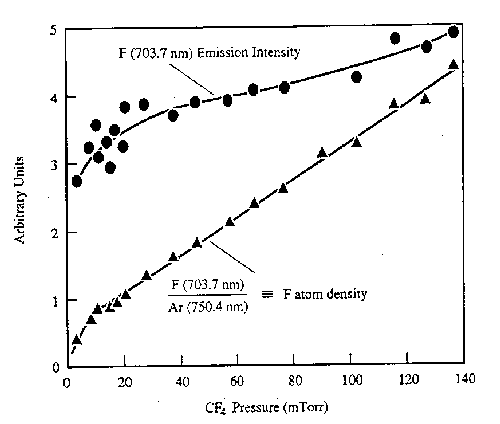
Fig. 3: F atom emission intensity (at 703.7 nm) and the F atom number density in a CF4 discharge deduced by actinometry, plotted as a function of pressure. (from J.W. Coburn and M. Chen, J. Vac. Sci. Technol. 18, 353 (1981)).
Many much more elaborate laser based diagnostics have been applied to the direct measurement of ground state species concentrations in a variety of plasmas (including work in the School of Chemistry at Bristol), but the complexity of such measurements means that they are generally restricted to research laboratories interested in the detailed science of the process rather than large scale plasma processing.
Many aspects of the basic theory of atomic transitions can be found for example in
B.P. Straughan and S. Walker eds. Spectroscopy, Vol. 1, Chapman and Hall, London.
and in many general textbooks, e.g. P.W. Atkins,Physical Chemistry, OUP.
A good reference for diatomic molecule spectroscopy is G. Herzberg, The Spectra and Structure of Simple Free Radicals, Cornell University Press.
Essential for conducting spectroscopy research into RF plasmas are the following compilations:
 Back to Introduction, forward to next lecture, or go to the Bristol Chemistry Home Page